4.5.4 Slot initiator alarm modules 6DR4004-6G and -8G
Function
If the standard controller requires electrically independent limit value messages, the slotted
initiator alarm module with slotted initiators is used instead of the alarm module.
● A binary output is used to display a collective fault message. Compare with the function of
the alarm module. The floating binary output is implemented as an automatic fault indicating
semiconductor output.
● The other two binary outputs are used to signal the two limits L1 and L2 which can be
adjusted mechanically using slotted initiators. Both these binary outputs are electrically
independent from the remaining electronic unit.
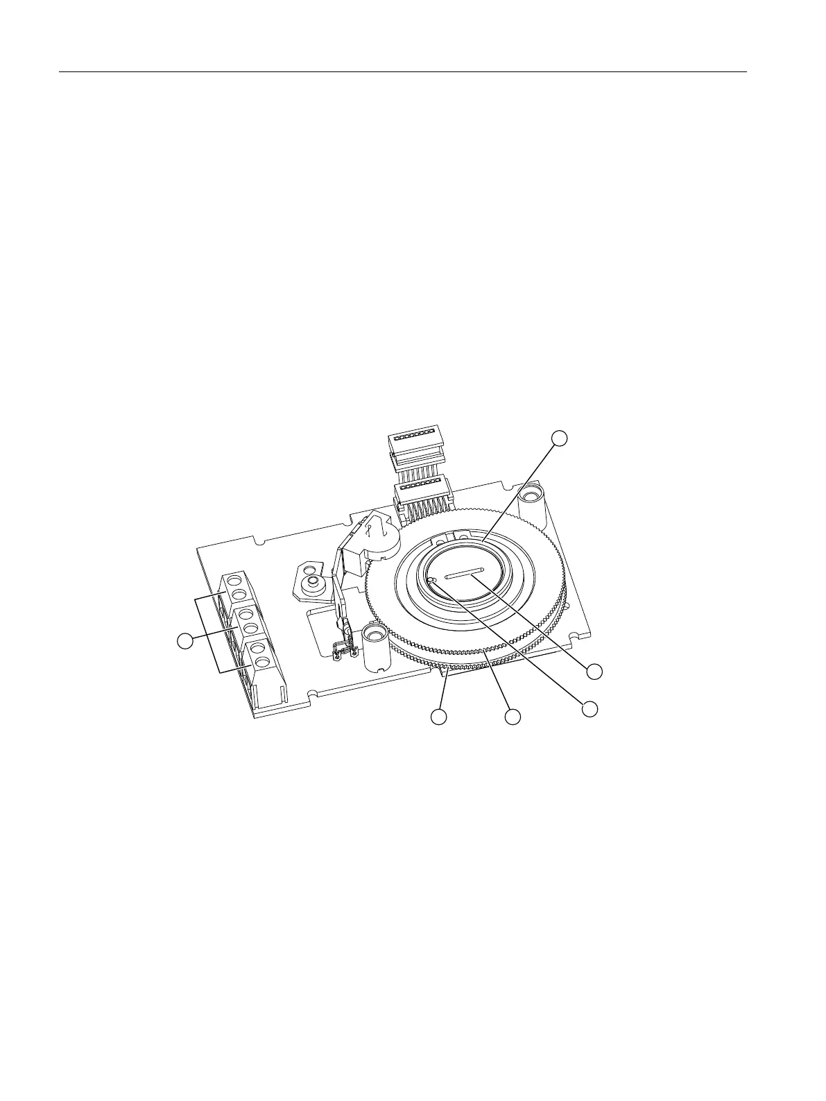
Device features
① Actuating disk bearings ② Special screw
③ Pin ④ Upper actuating disk for limit L1, terminals 41/42
⑤ Lower actuating disk for limit L2, termi‐
nals 51/52
⑥ Binary outputs
Figure 4-17 SIA module, schematic diagram
The slotted initiator alarm module, SIA module for short, consists of three binary outputs ⑥.
Requirement
● You are familiar with the procedure described in the section "General information about the
installation of option modules (Page 53)".
Installing/mounting
4.5 Installing the optional modules
SIPART PS2 with PROFIBUS PA
64 Operating Instructions, 05/2019, A5E00127926-AC

 Loading...


