The exhaust air outlet is corrosion-resistant for the blanketing of the pick-up room and the
spring chamber with dry instrument air.
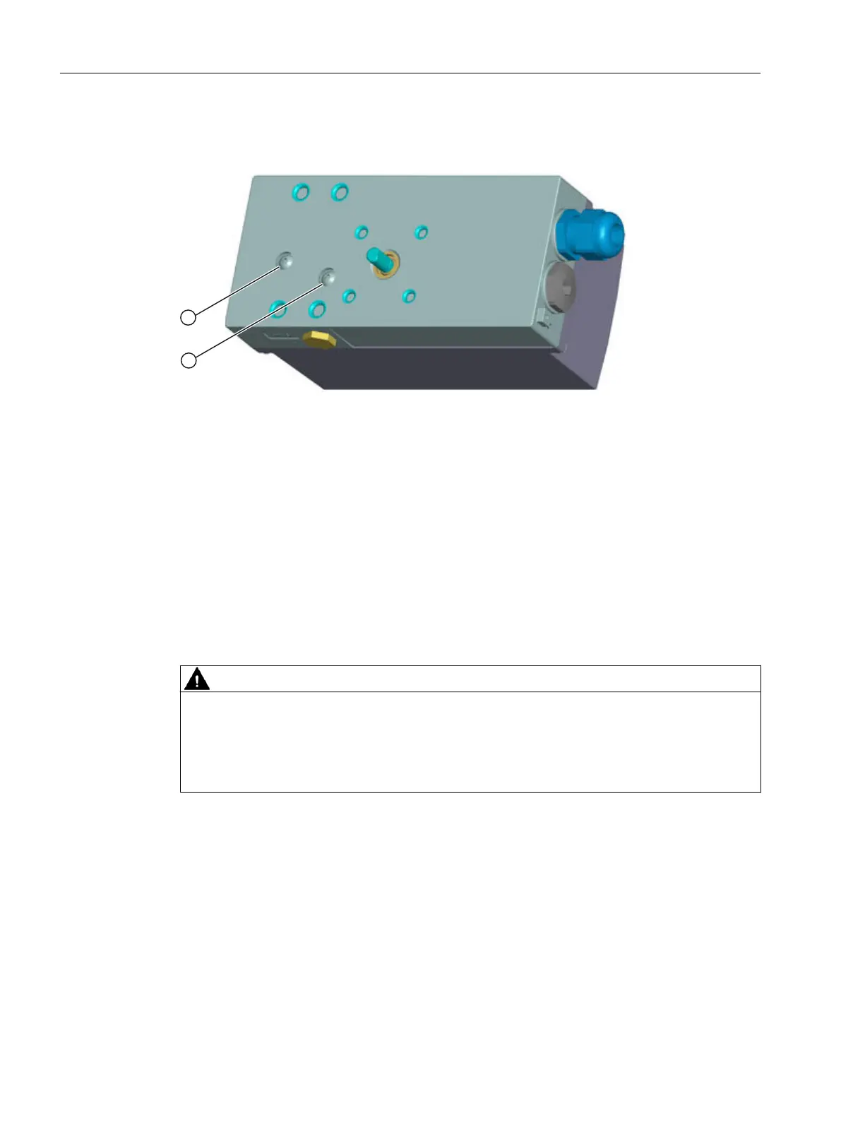
① Actuating pressure Y1
② Exhaust air outlet
Figure 5-12 Integrated pneumatic connection
5.3.3 Pneumatic connection in the flameproof enclosure
5.3.4 Reaction to failure of auxiliary powers
Overview
CAUTION
Before working on the control valve
Note that before working on the control valve, you must first move it to the safety position.
Make sure that the control valve has reached the safety position. If you only interrupt the
pneumatic auxiliary power supply to the positioner, the safety position may in some cases only
be attained after a certain delay period.
The difference between a failure of auxiliary pneumatic power and a failure of electrical auxiliary
power:
● Failure of electrical auxiliary power means:
– Failure of the bus voltage
– Failure or signal <4.5 V at input for the safety shutdown (terminals 82 and 82)
● Failure of auxiliary pneumatic power means the supply air PZ is interrupted.
Connect
5.3 Pneumatic connection
SIPART PS2 with PROFIBUS PA
94 Operating Instructions, 05/2019, A5E00127926-AC

 Loading...


