5.2 Electrical wiring
5.2.1 Connection diagram for basic electronics
$
(
([G([W([HF([L
9
352),
%863$
352),
%863$
352),
%863$
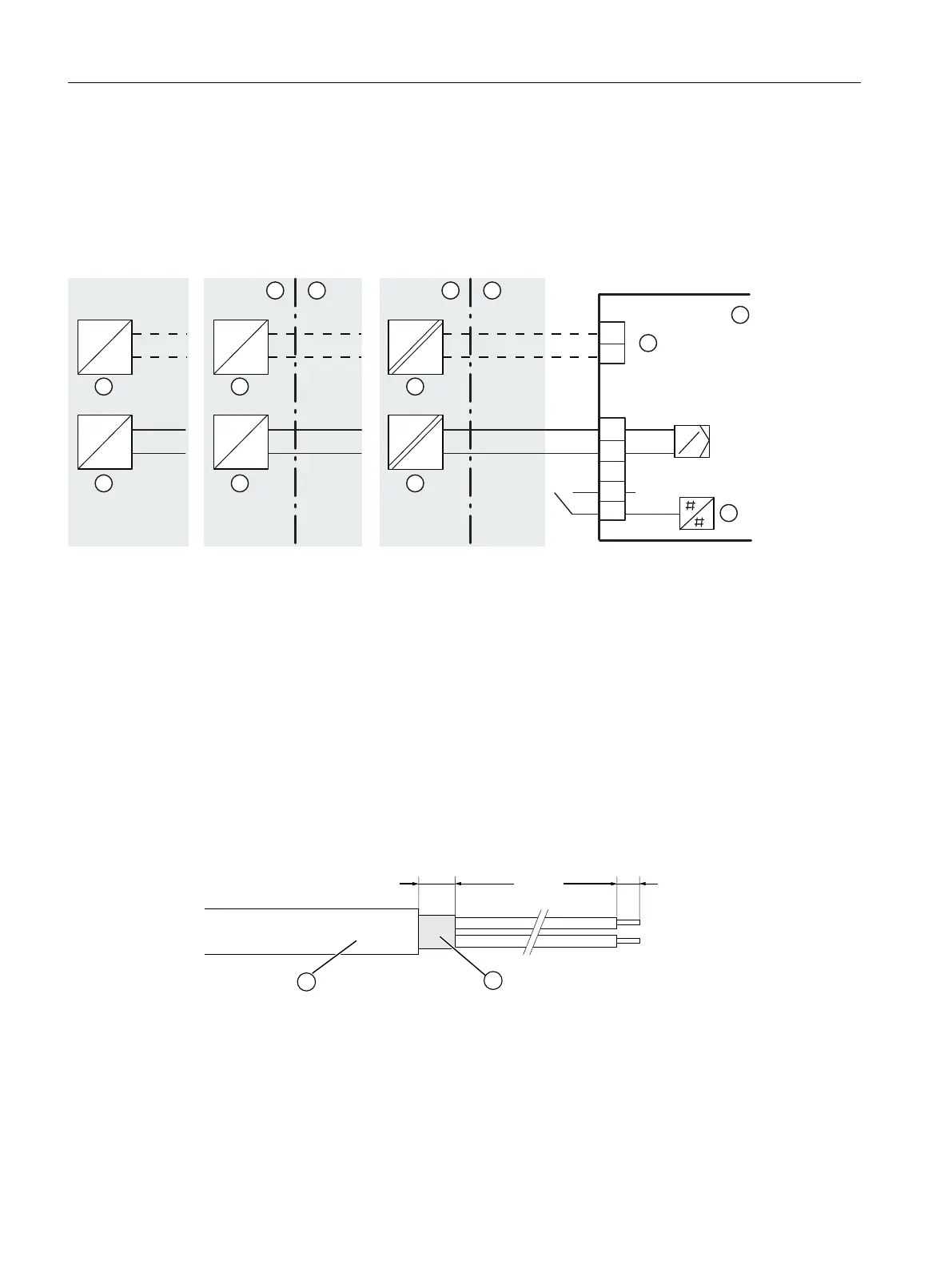
① Non-hazardous area ④ Input: Safety shutdown
② Hazardous area ⑤ Binary input 1
③ Basic electronics ⑥ Signal source
Figure 5-2 Device version with PROFIBUS PA
See also
Electrical specifications (Page 286)
5.2.2 Bus cable
The following image will help you in preparing the bus cable for the connection:
a 80 mm: Normal version of device
120 mm: Version with flameproof enclosure (6DR5..5)
① Bus cables to be used:
SIMATIC NET, PB FC Process Cable, bus cable for IEC 61158-2
② Cable shield
Figure 5-3 Preparation of bus cable
Connect
5.2 Electrical wiring
SIPART PS2 with PROFIBUS PA
82 Operating Instructions, 05/2019, A5E00127926-AC

 Loading...


