Functions
6.8 [2.09] Settings > Inputs/outputs
Operating with the Local User Interface
Operating Manual, 06/2017, A5E31930478-05
151
1. Main menu > "2. Settings" > "09. Inputs/outputs" > "4 DI links"
The menu includes eight navigation lines for digital input links. Each of these links can
access up to eight digital inputs or digital input links.
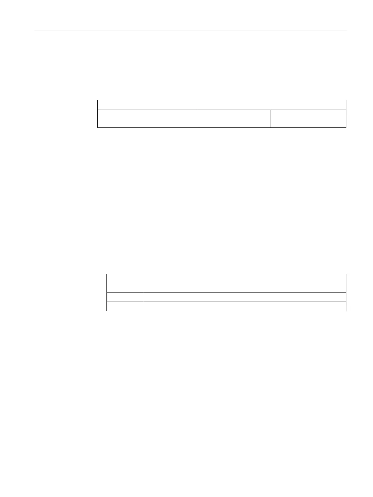
Structure of the navigation line for each DI link
Navigation no.
1)
DI name: Function
2)
3) 4)
Activation ID
5)
1)
Standard: Digital inputs 01 to 08. With option module 1 also: Digital inputs 17 to 20. With option
module 2 also: Digital inputs 09 to 16.
2)
Function triggered by the DI link. Depending on setting 3) or 4)
3)
If the DI link switches a measuring range, the component name is displayed.
4)
Message text of function at DI link = external fault, maintenance required, maintenance de-
manded, maintenance alarm, function check.
5)
Logical operation "AND" / "OR" or with deactivated link off.
2. Open selected DI link: Press <ENTER>.
The parameter display of a digital input whose parameters have not yet been assigned
includes parameter fields that you can use to define the type of link, the function
assignment as well as the objects to be linked.
3. Set the logic operation: "Type of logic operation" parameter field.
– Authorize access with Standard PIN, if necessary.
– Specify when the logic operation is activated:
Only one of the linked digital inputs must be enabled.
All linked digital inputs must be active.
Deactivates the logic operation.
4. Set up logic operations: parameter fields "1 to 8" of the "Inputs to be combined" group.
Select one of the digital inputs whose parameters are already assigned, or an existing
link.
 Loading...


