Home
Siemens
Measuring Instruments
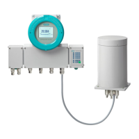
SIPROCESS GA700
Siemens SIPROCESS GA700 User Manual
4
of 1
of 1 rating
306 pages
Give review
Manual
Specs
To Next Page
To Next Page
To Previous Page
To Previous Page
Loading...
Description
3.4
CALO
MAT 7
Operating with the Local User Interface
Operating Manual
,
06/2017
,
A5E31930478
-
05
27
3.4
CALOMAT 7
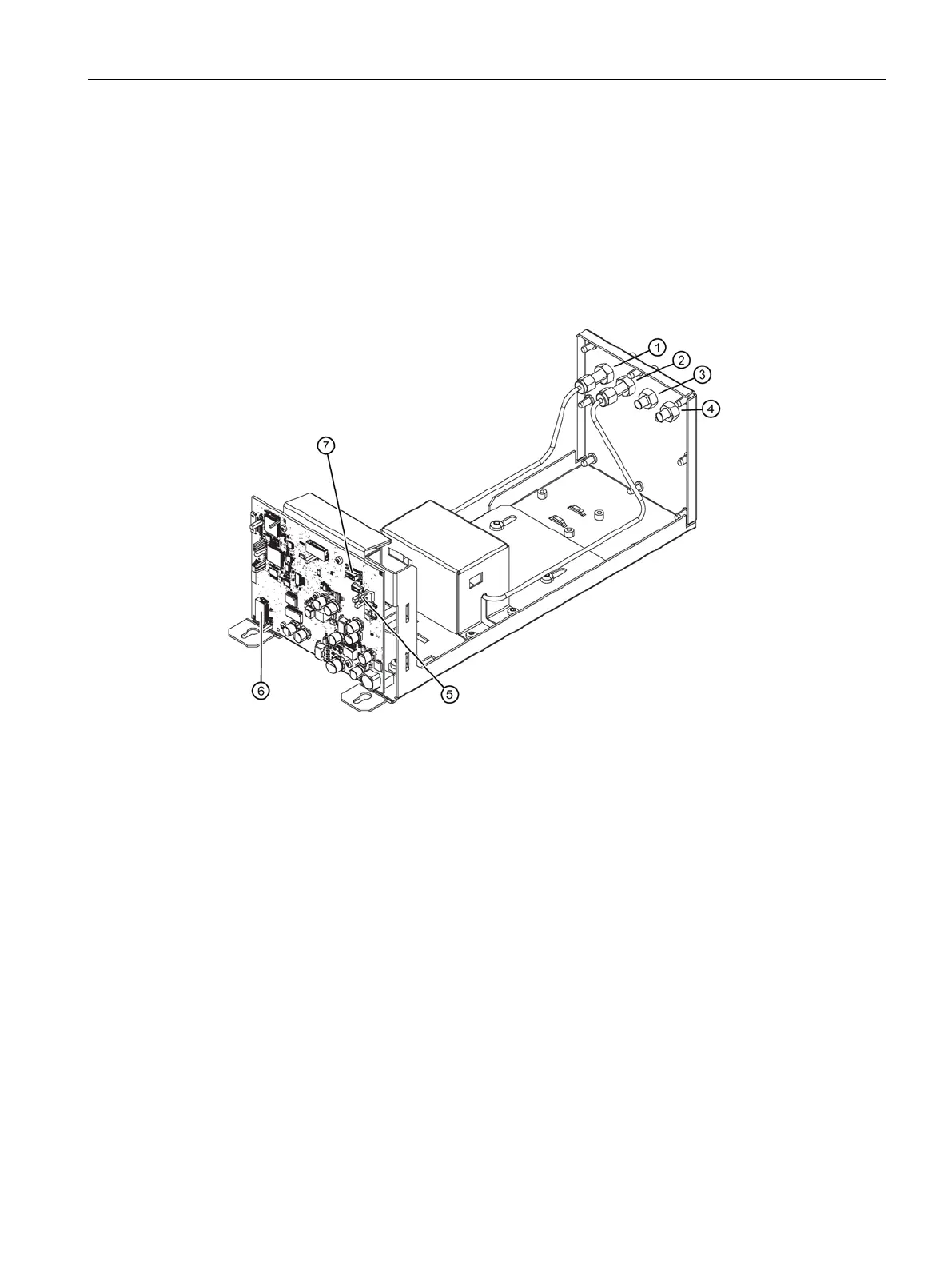
3.4.1
Design
Overview
①
Sample gas i
nlet
⑤
Power suppl
y connect
ion
②
Sample gas o
utlet
⑥
Analog output/
digital output
③
n.c.
⑦
CAN connecti
on
④
n.c.
Figure
3-5
Example: D
esign of CA
LOMAT 7, s
ample gas
path with
pipes
See also
How the C
ALOMAT 7
works
(
Page
28
)
26
28
Table of Contents
Table of Contents
3
Introduction
11
Purpose of this Documentation
11
History
11
Notes on Warranty
12
Target Group
12
Conventions
12
General Information
15
KC Safety Note - Information for Korea Only
15
Safety Instructions
15
Information on Use
16
Prerequisites for Safe Use
16
Security Messages
16
Communications
17
Qualified Personnel
17
Automatic Reset
17
Description
19
Overview
19
Oxymat 7
20
Design
20
Functional Principles
22
Ultramat 7
24
Design
24
How the ULTRAMAT 7 Works
25
Calomat 7
27
Design
27
How the CALOMAT 7 Works
28
CALOMAT 7 Measurement Task
28
Option Modules
30
Combined Operation
31
Analyzer Module/Installation Location Combinations
31
Safety Instruction(S)
31
Analyzer Module/Slot Combinations: Slots
33
Operating Modes
33
Setting Instructions
33
Operating Modes: Serial/Parallel Operation
34
Operating Modes: Selection of Operating Mode
35
Gas Connections
35
Safety Instruction(S)
35
Sample Gas Restrictors/Clamping Screws
37
Conditions for Use/Installation
40
Plug & Measure Permitted Activities
44
Plug & Measure
44
Setting Instructions
45
Case Differentiations
46
Operation
51
Local User Interface (LUI)
51
Keyboard
55
Structure
55
Key Functions
56
UNDO Function
58
UNDO Overview
58
Undo Actions with the <UNDO> Key
59
Display
60
Structure
60
Header
61
Display Area
63
Main View (Read Mode)
63
Main View (Selection Mode)
67
Navigational View
67
Parameter View
68
Status Bar
71
Menu Structure
72
Main Menu
72
Subordinate Menus
73
Commissioning
77
Requirements
77
Commissioning the SIPROCESS GA700
78
Functions
83
Quick Start
83
Quick Start Overview
83
Requirements
83
[1.1] Basic Settings
83
[1.2] Automatic Log-Off
85
Analog Outputs
86
[1.4] Measuring Ranges
88
Overview of Measuring Ranges
88
Setting the Measuring Ranges
89
Setting Autoranging
91
Calibration
92
Calibration/Validation Overview
92
Execute Calibration/Validation
96
[1.6] Save Parameter Set
98
Parameter Sets Overview
98
Save Parameter Set
98
[2.01] Settings >Display/User FUNC Key
98
Setting the Measured-Value Format
98
Setting the Extended Measured-Value Display
99
Displaying Additional Process Values
100
Customizing the Display Settings
101
Setting the Symbol Sets
101
Assigning USER FUNC Key
102
[2.02] Settings > Time/Date
102
Setting the Time and Date
102
[2.03] Settings > Measuring Ranges
103
Overview of Measuring Ranges
103
Setting the Measuring Ranges
105
Setting Autoranging
106
[2.04] Settings > Limits
107
Overview of Limits
107
Setting Limits
108
[2.07] Settings > Noise Suppression
111
Overview of Noise Suppression
111
Setting Noise Suppression
112
[2.08] Settings > Calibrations
114
Basics
114
Calibration/Validation
114
Sequence of a Calibration/Validation
116
Calibration Requirements
118
Overview
118
Permissibility of Calibrations
118
Non-Permissibility of Calibrations
119
[2.08.1] Setpoints, Tolerances, Purging Time
121
Overview
121
Setting the Setpoints
121
Setting Validation Tolerances
123
Setting the Calibration Tolerances
124
Setting the Sample Gas Purging Time
124
[2.08.2] Calibration Pool
126
Overview
126
Assigning Parameters for Calibration Pool Entries
126
[2.08.3] Execute Calibrations
128
[2.08.3.1] Use Calibration Pool
128
[2.08.3.2] Free Calibration
129
[2.08.4] Autocal/Autoval 1 and [2.08.5] Autocal/Autoval 2
131
Overview of Autocal/Autoval
131
Setting the Autocal/Autoval Sequence
132
Setting the Autocal/Autoval Mode
134
[2.09] Settings > Inputs/Outputs
137
[2.09.1] Analog Inputs
137
Overview
137
Set Analog Inputs
137
[2.09.2] Analog Output
141
Overview
141
Setting the Analog Outputs
142
[2.09.3] Digital Inputs
143
Overview of Digital Inputs
143
Setting Digital Inputs
148
[2.09.4] DI Links
150
Overview of DI Links
150
Linking Digital Inputs
150
[2.09.5] Digital Outputs
152
Overview
152
Functions
153
Setting Digital Outputs
155
Setting Functions/Components of a Digital Output
156
[2.10] Settings > Correction of Cross-Interferences
160
Overview
160
Correction Coefficients
160
Application Scenarios
161
Applications of OXYMAT 7
161
ULTRAMAT 7 Application Scenarios
163
CALOMAT 7 Application Scenarios
165
Setting Instructions
166
Setting the Correction of Cross-Interference
168
Oxymat 7
169
Assigning Correction of Cross-Interference with a Constant
169
Assigning Variable Correction of Cross-Interference
170
Ultramat 7
172
Assigning Correction of Cross-Interference with a Constant
172
Assigning Variable Correction of Cross-Interference
172
Calomat 7
174
Correction of Cross-Interference in the Application "H2 in N2 (Q)" for Furnace Gas, Converter Gas and Wood Distillation
174
Assigning Correction of Cross-Interference with a Constant
176
Assigning Variable Correction of Cross-Interference
177
Enabling/Disabling All Corrections of Cross-Interferences
179
[2.11] Settings > Pressure Sensor Selection
179
Overview
179
Setting Instructions
180
Using Device-Internal Pressure Sensor
181
Integrating External Pressure Sensor Via MODBUS TCP
182
Integrating External Pressure Sensor Via Analog Inputs
182
[2.12] Settings > Gas Path/Process Tag Label
183
[2.13] Setting > Process Tag Switchover
185
Setting the Process Tag Switchover
185
Assigning Process Tags
185
Enabling/Disabling All Process Tags
186
[2.14] Settings > Set Message Parameters
187
Set Message Parameters
187
Filtering Messages
188
Set Individual Message Parameters
189
[2.20] Settings > Service
190
[2.20.02] Heaters
190
[2.20.02] Heaters OXYMAT 7
190
[2.20.02] Heaters ULTRAMAT 7
190
[2.20.02] Heaters CALOMAT 7
190
[2.20.03] Factory Calibrations
190
Overview
190
Note on Setting
191
[2.20.03] Factory Calibrations OXYMAT 7
191
[2.20.03] Factory Calibrations ULTRAMAT 7
193
[2.20.03] Factory Calibrations CALOMAT 7
195
[2.20.04] Calibrate Pressure Sensor
196
Overview
196
[2.20.04] Calibrate Pressure Sensor OXYMAT 7
197
[2.20.04] Calibrate Pressure Sensor ULTRAMAT 7
198
[2.20.04] Calibrate Pressure Sensor CALOMAT 7
198
[2.20.06] Reference Gas Pump OXYMAT 7
199
[2.20.10] Name/Unit
200
[2.20.11] Physical Measuring Range
201
12] Switch Message System Off/On
202
[3.01] Maintenance & Diagnostics > Current Messages
203
Displaying Current Messages
203
Filtering Current Messages
204
Reading Current Messages
205
[3.02] Maintenance & Diagnostics > Messages to be Acknowledged
206
Displaying Messages to be Acknowledged
206
Acknowledge Message
207
Acknowledge All Messages
208
[3.03] Maintenance & Diagnostics > Logbook
209
Overview of Logbook
209
[3.03.1] Display Logbook
212
[3.03.1] Filter Logbook Entries
213
[3.03.2] Delete Logbook
214
[3.04] Maintenance & Diagnostics > Measured Value Status
214
[3.05] Maintenance & Diagnostics > Diagnostics Values
215
[3.05.1] Measured Signal Diagnostics
215
Measured Signal
215
Heating Controller
217
[3.05.2] Predictive Self-Diagnostics ULTRAMAT 7
218
[3.05.3] Electric Parameters
219
[3.05.4] Inputs/Outputs
221
Analog Inputs
221
Analog Outputs
221
Digital Inputs
222
4] Digital Outputs
222
[3.05.5] Communications
223
MODBUS TCP Node
223
MODBUS TCP Digital Inputs
224
[3.05.6] Operating Hours Counter
224
[3.06] Maintenance & Diagnostics > Drift Values
225
Editing Zero Point Drift Values
225
Editing QAL3 Drift Values
226
Displaying Control Reserve
226
[3.08] Maintenance & Diagnostics > Maintenance Intervals
227
Displaying Maintenance Intervals
227
Assigning Maintenance Interval Parameters
227
[3.09] Maintenance & Diagnostics > Identification
229
Overview
229
Identifying a Device
230
Identifying Analyzer Modules
231
Identifying Additional Features
232
Identify Sensor Module CALOMAT 7
232
Identifying Option Modules
233
[3.10] Maintenance & Diagnostics > Save/Load Parameter Set
233
Overview
233
Save Parameter Set
234
Load Parameter Set
235
[3.11] Maintenance & Diagnostics > Test
236
Overview of Test
236
[3.11.1] Test Inputs/Outputs
236
Testing of Analog Outputs
236
Testing Analog Inputs
238
Testing of Digital Outputs
241
Testing of Digital Inputs
243
[3.11.2] Test Display
244
[3.11.3] Test Keyboard
244
[3.11.4] Test Internal Communication
244
[3.12] Maintenance & Diagnostics > Cold Restart
245
[3.20] Maintenance & Diagnostics > Service Trace
245
Communications
245
Overview
245
Setting Communication Via Ethernet
247
Setting Communication Via MODBUS TCP
248
Setting MODBUS Digital Inputs
249
5] Security
251
Assigning / Changing Personal Identification Numbers (PIN)
251
Automatic Log-Off
251
6] Language
253
Alarm, Error, and System Messages
255
LUI Symbol Sets
255
OXYMAT 7 Message List
257
ULTRAMAT 7 Message List
264
CALOMAT 7 Message List
269
Wizard-Based Error Messages
273
Measured Value Status
276
Messages
276
Symbolic Representation
278
Appendix
279
Technical Support
279
Approvals
280
Conformity with European Directives
280
Certificate
281
References
281
Modbus Tcp
284
MODBUS Interface for SIPROCESS GA700
284
Planning/Configuring
285
Transfer of Device Data
288
Device Data
288
Device Data: Extras
298
Index
303
Other manuals for Siemens SIPROCESS GA700
Quick Start
142 pages
Operating Instructions
200 pages
Compact Operating Instructions
118 pages
4
Based on 1 rating
Ask a question
Give review
Questions and Answers:
Need help?
Do you have a question about the Siemens SIPROCESS GA700 and is the answer not in the manual?
Ask a question
Siemens SIPROCESS GA700 Specifications
General
Brand
Siemens
Model
SIPROCESS GA700
Category
Measuring Instruments
Language
English
Related product manuals
Siemens SICAM
174 pages
Siemens SITRANS F
306 pages
Siemens SITRANS SL
212 pages
Siemens SITRANS F M
24 pages
Siemens SIRIUS 3RN2
70 pages
Siemens SIMEAS R-PMU
296 pages
Siemens SICAM 7KG85X
281 pages
Siemens SITRANS F US
52 pages
Siemens SITRANS FC330
280 pages
Siemens SITRANS FS130
118 pages
Siemens SITRANS FX300
80 pages
Siemens SITRANS FUS080
95 pages
 Loading...


