3、INTAKE SYSTEM COMPONENT 23
CHK
A
DJ
NO. PART NO. PART NAME QTY CAUTION
1 1250306-006097
(
)
2 1251500-007091
Non-standard flat mat φ10.5×φ24×2
(
)
3 1251100-101000
(
)
4 1274100-057095
flanging bushing φ6.2×φ8.5×3.5
+
5 1244100-052000 buffer rubber of flanging bushing (φ8.5×φ14×1) 3
7 1251100-102000
(
)
8 1224200-110000 ZT310-V rear inner mud plate 1
A B
C D
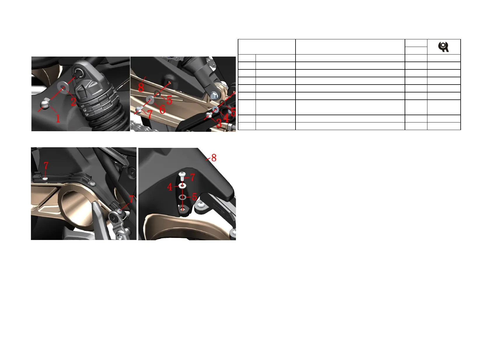
PROCEDURE:
●Side cover
Refer to the method of removing the right cover on the previous page, remove the left and right covers.
●Left rear shock absorption
Remove the nut ⑴ with the sleeve,then remove the flat mat⑵.
●Back inner mud board
Remove the bolts ⑶ and ⑺ on the left side, remove the bushings ⑷ and ⑹ , and then remove the cushion
rubber ⑸ .
Remove the wheel speed sensor wire and the rear brake caliper tubing from the tubing clamp and remove the
two bolts ⑺ shown.
Remove the bolt ⑺ on the inside of the front and remove the bushing ⑷before removing the cushion rubber ⑸.
Pull the left rear shock absorbing head outward and remove the rear inner mud plate ⑻.
CAUTION:
● Do not pull out the stud end face completely when pulling the rear shock absorber head.
● Pay attention to the force when pulling out the wheel speed sensor line and the oil pipe.
● The bolt in the middle of the front right side (Figure C) cannot be removed.
Fig.9 INDUCTION
SYSTEM COMPONENT
Replace the air filter element (Bosch) 1
6 1251700-059093
flanging bushingφ6.4×φ9×8+φ18×2(environmental
color)
1
 Loading...