EasyManua.ls Logo

Allen-Bradley SmartGuard 600 User Manual

Allen-Bradley SmartGuard 600
240 pages
To Next Page IconTo Next Page
To Previous Page IconTo Previous Page
Page #84 background imageLoading...
Page #84 background image
Publication 1752-UM001A-EN-P - October 2006
84 Create Your Application Program
You can password-protect your application program to prevent
unauthorized editing, verification, or printing of programs. To create a
password, follow these steps.
1. On the Logic tab of the Controller Properties dialog, check the
Enable Password checkbox.
2. On the Change Password dialog, type in the password in the
New Password field.
Passwords may contain up to six characters.
3. Re-type the password in the Confirm Password field.
4. Click OK.
The password will be requested whenever the Edit button is clicked
to open the Logic Editor. You can upload or download the program
without the password, but program edit, verification, print and report
functions are not available.
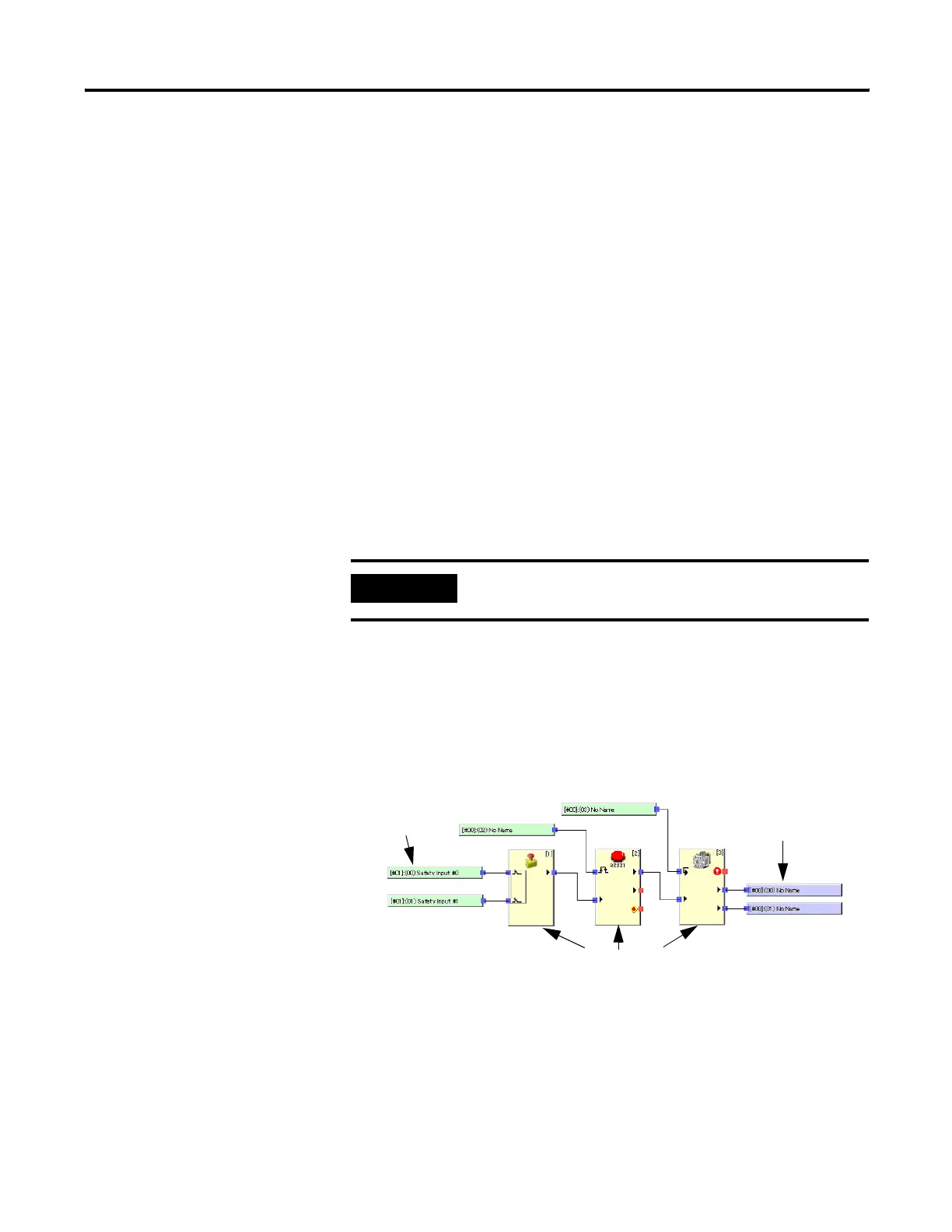
Programming Basics
Programs are created from logic functions and function blocks that
indicate commands, from input tags that indicate data input sources,
and from output tags that indicate data output destinations. The I/O
are connected with connection lines.
I/O Connections
IMPORTANT
If you forget the password, it cannot be recovered.
Input Tags
Output Tags
Function Blocks

Table of Contents

Question and Answer IconNeed help?

Do you have a question about the Allen-Bradley SmartGuard 600 and is the answer not in the manual?

Allen-Bradley SmartGuard 600 Specifications

General IconGeneral
ModelSmartGuard 600
TypeSafety Controller
Input Voltage24 VDC
SIL RatingSIL 3
PL RatingPL e
CategoryCategory 4
Standard Outputs4
Communication ProtocolsEtherNet/IP
Response Time10 ms
Storage Temperature-40°C to 85°C
Relative Humidity5% to 95% (non-condensing)
DimensionsVaries depending on the specific module configuration. Check documentation for exact dimensions.
WeightVaries by model

Summary

Important User Information

Chapter 1 Overview

Introduction to SmartGuard 600 Controller

Overview of the SmartGuard 600 controller's capabilities and certifications.

SmartGuard 600 Controller Hardware

Details the physical features and components of the SmartGuard 600 controller.

Communications Overview

Explains the controller's communication capabilities via DeviceNet and USB.

Configuration and Programming

Outlines how to configure, program, and monitor the controller using software.

Status and Error Monitoring

Describes how to monitor controller status and diagnose errors using LEDs and software.

Safety Concept of the Controller

Details the controller's safety certifications and mechanisms for data integrity.

Additional Resources for SmartGuard

Lists related publications for further information on SmartGuard systems.

Chapter 2 Installing and Wiring the SmartGuard 600 Controller

Introduction to Installation and Wiring

Overview of the chapter's topics on installing and wiring the controller.

General Safety Information and Environment

Critical safety guidelines for installation, environment, and hazardous locations.

Understanding Node Addressing

Explains the importance of node addresses for DeviceNet communication.

Setting the Node Address

Step-by-step instructions for configuring the controller's node address.

Setting the Communication Rate

How to configure the DeviceNet communication rate and its parameters.

Mounting the SmartGuard Controller

Guidelines and procedures for properly mounting the controller on a DIN rail.

Grounding the SmartGuard Controller

Procedures for providing an acceptable grounding path for the controller.

Connecting the Power Supply

Information on powering the controller with a 24V DC source and compliance.

Wiring Input Devices

Instructions for connecting various input devices like switches and sensors.

Wiring Output Devices

Guidance on connecting output devices and loads to the controller.

Wiring Examples

Illustrative wiring diagrams for common safety applications like ESTOP and Safety Gate.

Chapter 3 Set Up Your DeviceNet Network

Connecting a Computer to DeviceNet

Steps to establish network connectivity between a computer and the DeviceNet network.

Configuring Network Drivers

How to configure necessary drivers in RSLinx software for network communication.

Commissioning DeviceNet Nodes

Procedures for commissioning devices on the DeviceNet network using RSNetWorx.

Browsing the DeviceNet Network

Steps to browse and verify the network configuration and device visibility.

Understanding Configuration Signature

Explains the unique signature used to verify device configuration integrity.

Performing a Safety Reset (Optional)

How to reset safety device attributes to their default state.

Setting Device Passwords (Optional)

Procedures for protecting device configuration with passwords.

Chapter 4 Manage the Safety Network Number

Introduction to Safety Network Numbers

Explains the purpose and importance of Safety Network Numbers (SNNs).

Safety Network Number (SNN) Formats

Describes the two formats for assigning SNNs: time-based and manual.

Assigning Safety Network Numbers (SNN)

Details automatic (time-based) and manual methods for assigning SNNs.

Setting SNN in All Safety Nodes

Steps to automatically assign SNNs to all safety nodes on the network.

Handling SNN Mismatches

How to identify and resolve discrepancies between online and offline SNNs.

SNN and Node Address Changes

Procedures for managing SNN and node address changes, including safety resets.

Chapter 5 Configure Local I/O

Configuring Local Safety Inputs

Detailed steps for configuring the controller's 16 local safety inputs.

Configuring Local Test Outputs

Instructions for setting up the controller's four independent test outputs.

Configuring Local Safety Outputs

Detailed steps for configuring the controller's eight local safety outputs.

Chapter 6 Configure Your Controller for DeviceNet Communications

Setting Up as a DeviceNet Safety Master

How to configure the controller to act as a master for safety I/O communications.

Setting Up as a DeviceNet Safety Slave

How to configure the controller to act as a slave for safety I/O communications.

Setting Up as a DeviceNet Standard Slave

How to configure the controller to act as a slave for standard I/O communications.

Chapter 8 Create Your Application Program

Introduction to Application Programming

Overview of creating application programs using the Logic Editor.

Using the Logic Editor

Explanation of the Logic Editor interface for programming the controller.

Programming Basics and I/O Connections

Fundamental concepts of programming, logic functions, and I/O tag connections.

Creating Function Block Programs

Steps for creating programs using function blocks and connecting tags.

Editing Function Block Parameters

How to modify parameters and settings of function blocks.

Finding Function Blocks with Open Connections

Method to locate function blocks with unconnected inputs or outputs.

Programming on Multiple Pages

Techniques for organizing programs across multiple pages using jump addresses.

Saving and Updating Programs

Procedures for saving, applying, and updating the controller program.

Monitoring the Program Online

How to monitor I/O tag values and signal states in real-time.

Understanding Program Execution Sequence

How the Logic Editor sets the order of function block execution.

Creating User-defined Function Blocks

Steps to create, define, and reuse custom function blocks.

Additional Resources for Programming

Lists appendices with command references for logic functions and function blocks.

Chapter 9 Download and Verify

Downloading DeviceNet Network Configuration

Steps to download the network configuration to devices using RSNetWorx.

Verifying DeviceNet Safety Configuration

How to verify the safety configuration of devices using the Safety Device Verification Wizard.

Starting the Safety Device Verification Wizard

Steps to launch the wizard for device verification and safety-locking.

Determining Verifiable Devices

How the wizard identifies devices that can be verified based on their status.

Selecting Devices for Verification

Process of selecting specific devices within the wizard for verification.

Reviewing Safety Verification Reports

How to review and print verification reports for record-keeping.

Locking Safety Devices

Procedures to safety-lock devices after successful verification.

Viewing the Verification Wizard Summary

How to view a summary of the safety device verification and locking process.

Chapter 10 Monitor Status and Handle Faults

LED Indicators for Status

Description of module, network, and I/O status LEDs and their meanings.

Alphanumeric Display for Status

Information provided by the controller's alphanumeric display regarding operational state.

Monitoring I/O Power Supply Input

How to check the I/O power supply status using the alphanumeric display.

Monitoring I/O Maintenance Information

Configuring and using maintenance modes for contact operation and total on-time monitoring.

Viewing I/O Status Data

How to view status information for safety and standard slave I/O data.

Controller Connection Status (Safety Slave)

Interpreting connection status codes and corrective actions for safety slave function.

Understanding Error Categories

Classification of controller errors into nonfatal, abort, and critical types.

Error History Table and Memory

How errors are recorded and displayed in the controller's error history.

Error History Messages and Corrective Actions

Details on interpreting error messages and implementing corrective actions.

Download Errors and Corrective Actions

Troubleshooting guide for errors occurring during configuration data downloads.

Reset Errors and Corrective Actions

Guidance on resolving errors encountered during controller reset operations.

Mode Change Errors and Corrective Actions

Troubleshooting for errors related to changing controller operating modes.

Appendix A Status Indicators

Interpreting Status LED Indicators

Guide to understanding the color and state combinations of controller status LEDs.

Identifying Errors Using Status Indicators

Tables to interpret LED and alphanumeric display indicators for error diagnosis.

Appendix B Logic Functions Command Reference

Introduction to Logic Functions

Overview of logic functions used in programming.

NOT Logic Instruction

Explanation and truth table for the NOT logic instruction.

AND Logic Instruction

Explanation and truth tables for the AND logic instruction.

OR Logic Instruction

Explanation and truth tables for the OR logic instruction.

Exclusive OR Logic Instruction

Explanation and truth tables for the Exclusive OR logic instruction.

Exclusive NOR Logic Instruction

Explanation and truth tables for the Exclusive NOR logic instruction.

Routing Logic Instruction

Explanation and truth table for the Routing logic instruction.

Reset Set Flip-flop (RS-FF) Instruction

Explanation of the RS-FF instruction for state management.

Multi-connector Instruction

Explanation of the Multi-connector instruction for signal routing.

Comparator Instruction

Explanation and parameters for the Comparator logic instruction.

Appendix C Function Blocks Command Reference

Reset Function Block

Details the Reset function block, its parameters, and timing.

Restart Function Block

Details the Restart function block, its parameters, and timing.

Emergency Stop (ESTOP) Function Block

Explanation of the ESTOP function block for emergency stop monitoring.

Light Curtain (LC) Function Block

Details the Light Curtain function block for monitoring safety light curtains.

Safety Gate Monitoring Function Block

Explanation of the Safety Gate Monitoring function block for gate status.

Two-hand Control Function Block

Details the Two-hand Control function block for monitoring two-hand switches.

OFF-delay Timer Function Block

Explanation of the OFF-delay timer function block.

ON-delay Timer Function Block

Explanation of the ON-delay timer function block.

User Mode Switch Function Block

Details the User Mode Switch function block for monitoring operating mode switches.

External Device Monitoring (EDM) Function Block

Explanation of the EDM function block for monitoring external device feedback.

Muting Function Block

Details the Muting function block for temporarily disabling light curtains.

Enable Switch Function Block

Explanation of the Enable Switch function block for monitoring enable-switch devices.

Pulse Generator Function Block

Details the Pulse Generator function block for creating pulse outputs.

Counter Function Block

Explanation of the Counter function block for counting input pulses.

Appendix D Explicit Messages

Introduction to Explicit Messages

Overview of explicit messaging for data exchange with the controller.

Receiving Explicit Messages

Details on how the controller receives and responds to explicit messages from masters.

Sending Explicit Messages

How the controller can send explicit messages based on trigger conditions.

Accessing Controller Parameters via Explicit Messages

How to read and write controller parameters using DeviceNet explicit messages.

Appendix E Application and Configuration Examples

Emergency Stop Application Example

Example of configuring a dual channel emergency stop switch with manual reset.

Safety Gate Application with Automatic Reset

Example of setting up dual channel limit switches with automatic reset.

Dual Zone Safety Gate with E-stop Example

Example of dual zone gates with E-stop and manual reset for zoned operation.

Safety Mat Application Example

Example of a safety mat application with manual reset and E-stop.

Light Curtain Application Example

Example of a light curtain application with manual reset and E-stop.

Related product manuals