Publication 1752-UM001A-EN-P - October 2006
56 Configure Local I/O
Configure Local Safety
Outputs
The controller has eight local safety outputs that support the functions
listed below.
• Output circuit diagnosis — Test pulses can be used to diagnose
the controller’s internal circuits, external devices, and external
wiring.
• Overcurrent detection and protection — To protect the circuit,
an output is blocked when an overcurrent is detected.
• Dual Channel mode — Both of two paired outputs can be set
into a safety state when an error occurs in either of the two
paired local outputs without depending on the user program.
Follow these steps to configure a local safety output.
1. Right-click the SmartGuard controller and choose Properties.
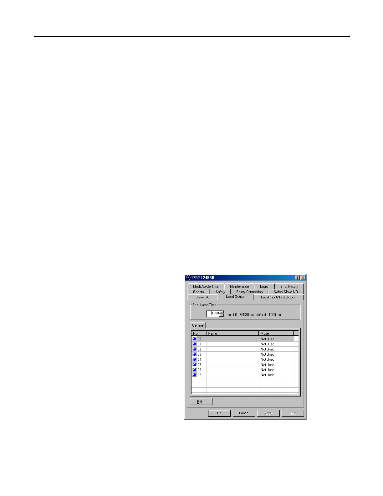
2. Select the Local Output tab.
3. Set the Error Latch Time.
The error latch time applies to all safety outputs. It sets the time
to latch the error state when an error occurs in an input or
output. Even if the error is removed, the error state is always
latched for the configured error latch time. The error latch time
is set from 0…65530 ms in 10 ms increments. The default is
1000 ms.

 Loading...


