Publication 1752-UM001A-EN-P - October 2006
Installing and Wiring the SmartGuard 600 Controller 29
Wire Input Devices
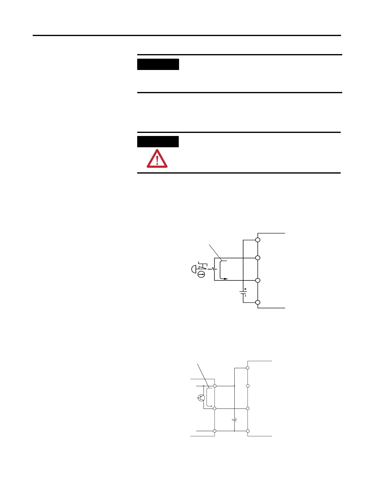
Input devices with mechanical contact outputs, such as emergency
stop buttons and safety limit switches, use both a safety input terminal
and a test output terminal. This enables the circuit to reach a Category
4 rating.
Input Devices with Mechanical Contact Outputs
Devices, such as light curtains, with current-sourcing PNP
semiconductor outputs send a signal to the SmartGuard 600 controller
safety input terminal and do not use a test output.
Input Devices with PNP Semiconductor Outputs
IMPORTANT
Prepare stranded wires by attaching ferrules with plastic
insulation covers (compliant with the DIN 46228-4 standard).
Ferrules similar in appearance but not compliant may not match
the terminal block on the controller.
ATTENTION
Applying an inappropriate DC or any AC voltage may result in a
loss of safety function, product damage, or serious injury.
Properly apply only the specified voltage to controller inputs.
SmartGuard 600
Controller
V1
Tx
INx
G1
24V dc
4.5 mA Typical
SmartGuard 600
Controller
V1
Tx
INx
G1
24V dc
24V dc
OSSDx
GND
4.5 mA Typical

 Loading...


