Publication 1752-UM001A-EN-P - October 2006
Installing and Wiring the SmartGuard 600 Controller 25
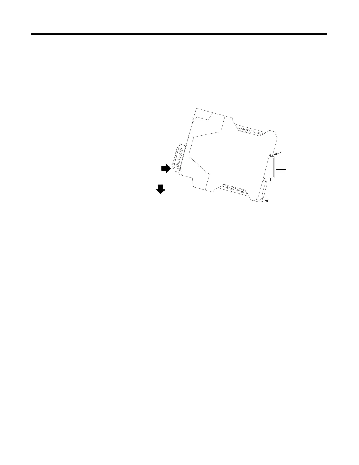
The controller cannot be panel-mounted. Follow these steps to mount
the controller to an EN50022-35x7.5 or EN50022-35x15 DIN rail.
1. Hook the top slot over the DIN rail.
2. Snap the bottom of the controller into position while pressing
the controller down against the top of the rail.
3. Attach end plates to each end of the DIN rail.
To remove the controller from the DIN rail, use a flathead screwdriver
to pull down the latch and lift the controller off of the rail.
Grounding the SmartGuard
Controller
You must provide an acceptable grounding path for each device in
your application. Functionally ground the controller through its V0/G0
power connection.
Refer to the Industrial Automation Wiring and Grounding Guidelines,
publication 1770-4.1, for additional information.
Connecting a Power Supply
Power for the controller is provided via an external 24V dc power
source. The output hold time must be 20 ms or longer.
To comply with the CE Low Voltage Directive (LVD), DeviceNet
connections and I/O must be powered by a dc source compliant with
Safety Extra Low Voltage (SELV) or Protected Extra Low Voltage
(PELV).
Latch
Latch
DIN Rail

 Loading...


