Publication 1752-UM001A-EN-P - October 2006
152 Logic Functions Command Reference
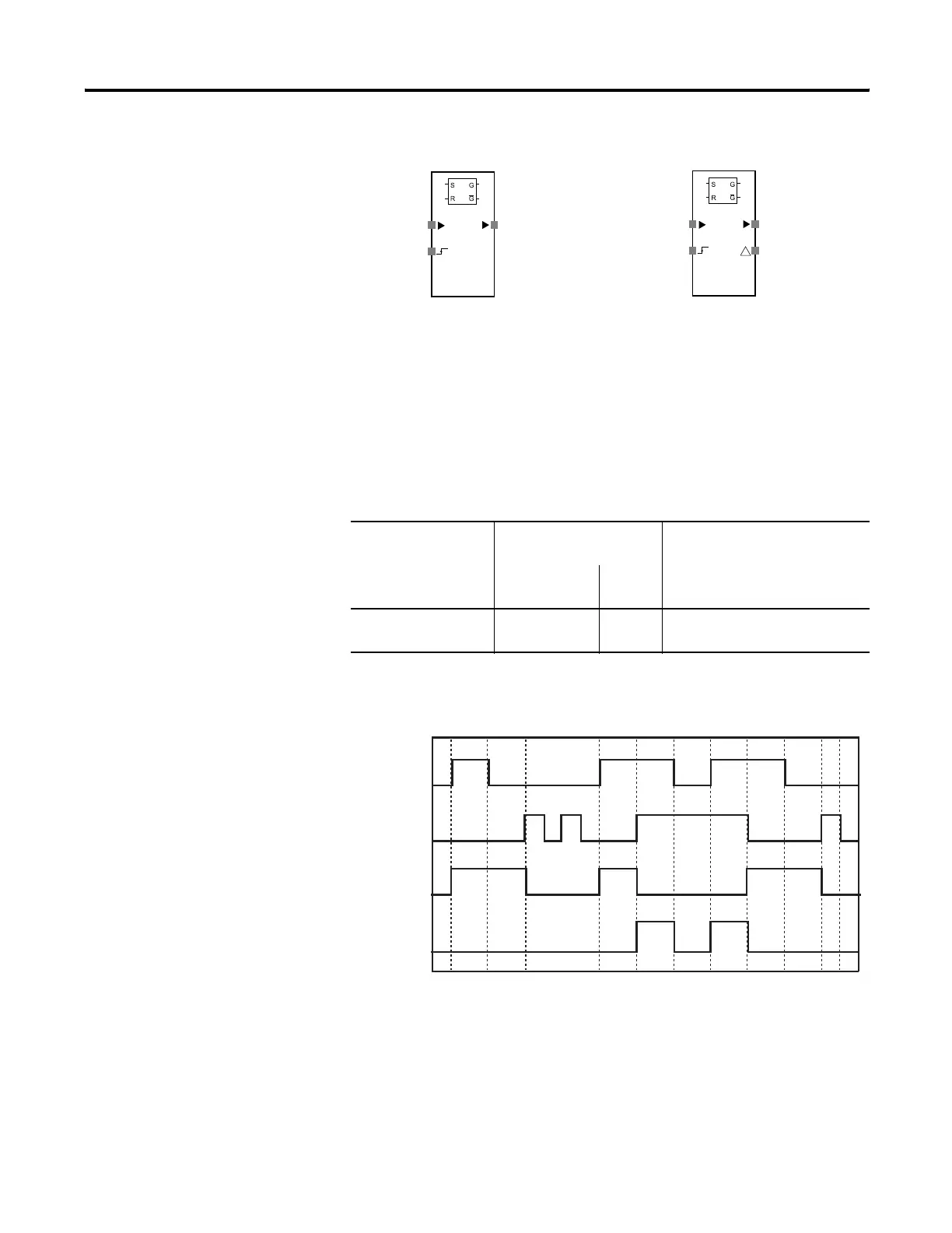
Reset Set Flip-flop Instruction Diagram
Reset Set FIip-flop Error Handling
Use this table to diagnose and reset a discrepancy error condition in
the RS Flip-flop instruction.
RS Flip-flop Instruction Timing Chart
Multi-connector Instruction
The Multi-connector instruction converts input signals for up to eight
inputs into output signals for up to eight outputs. The input signals
and output signals are associated one-to-one for signals one to eight.
The status of other input signals has no effect.
Error Detection and Reset for RS Flip-flop Instruction
Error Condition Status When an Error
Occurs
To Reset the Error Condition
Output Enable Fault
Present
Input and Reset are
active simultaneously
OFF
(Safety State)
ON Make one of the signals inactive.
!
Output EnableInput
Reset
Default Connections Maximum Inputs for Reset Set Flip-Flop Function
Output EnableInput
Reset Fault Present
Input
Fault Present
Output
Enable
Reset

 Loading...


