Publication 1752-UM001A-EN-P - October 2006
156 Logic Functions Command Reference
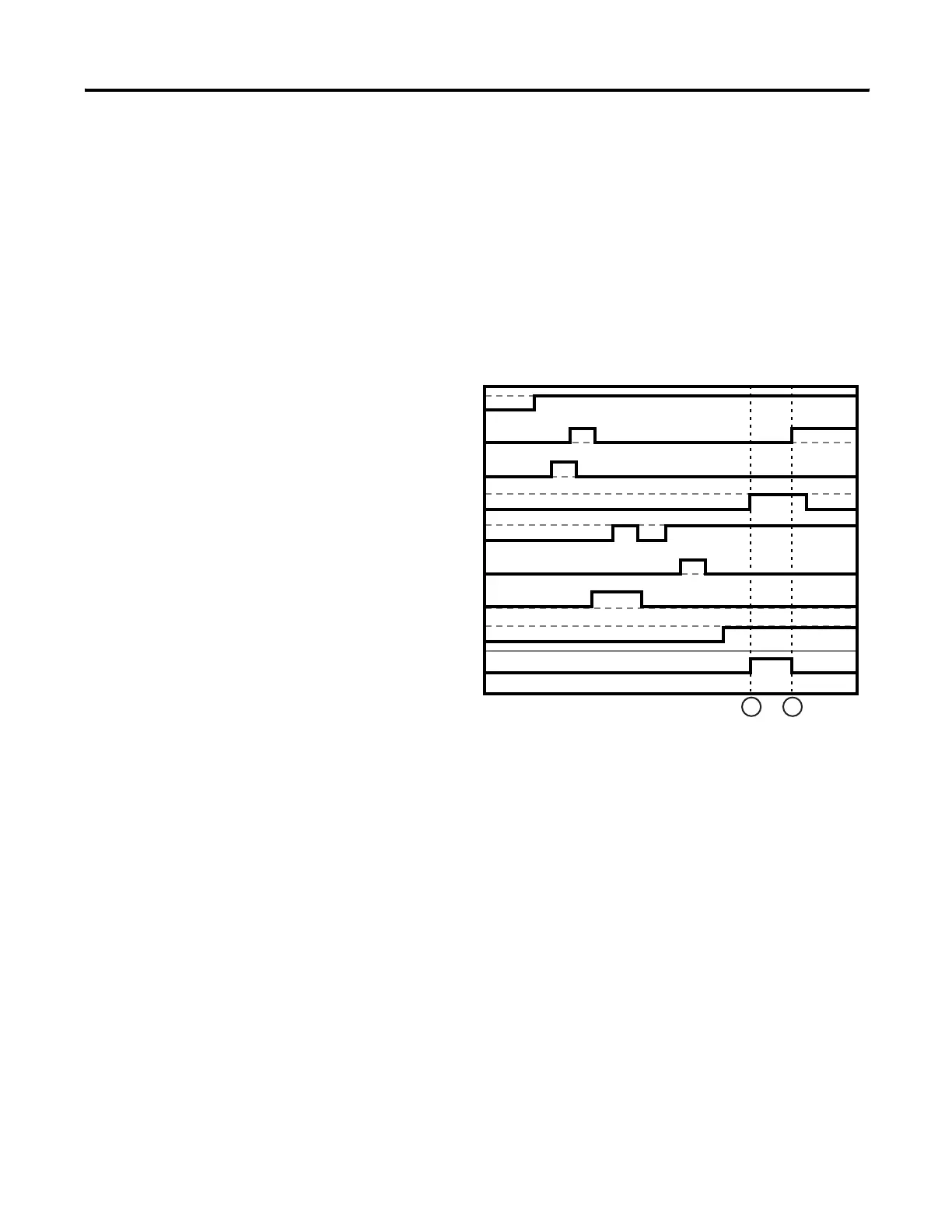
Comparator Instruction Timing Chart
The horizontal dashed lines in the chart represent the comparison
values (CV) for each input.
1. Output 1 turns on when all of the input signals match the
comparison value.
2. Output 1 turns off when any of the input signals does not match
the comparison value.
Comparator Timing Chart
1 2
Input 1
Output 1
Input 2
Input 3
Input 4
Input 5
Input 6
Input 7
Input 8

 Loading...


