Publication 1752-UM001A-EN-P - October 2006
52 Configure Local I/O
9. Specify an On Delay time and an Off Delay time.
The valid range is 0…126 ms, but the delay time must be a
multiple of the cycle time.
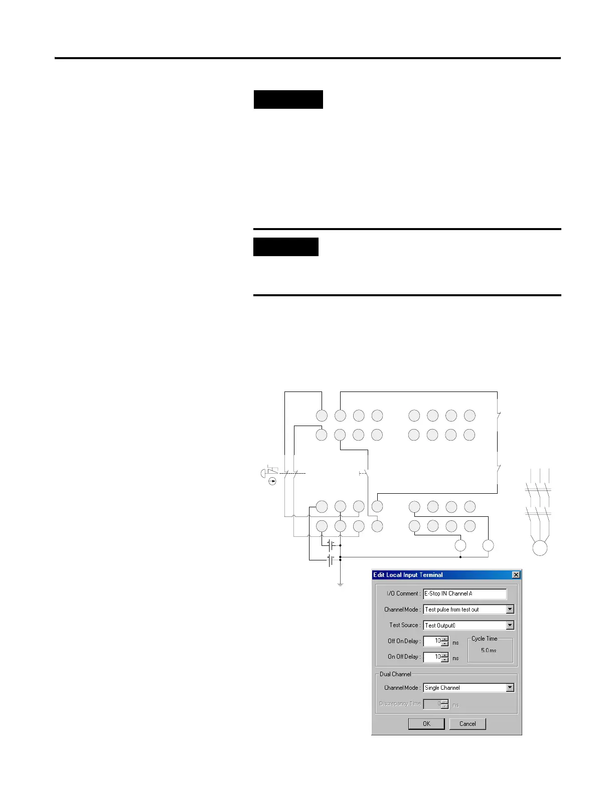
Example: Input Channel as Test Pulse from Test Output
For the following wiring diagram, the channel mode must be
configured as Test pulse from test out, as shown.
TIP
The controller supports function blocks with
functionality equivalent to Dual Channel mode.
If Dual Channel mode is set in a function
block, the safety input terminal can be set to
Single Channel mode.
IMPORTANT
The optimum value for controller cycle time is
automatically calculated based on the parameter settings
and the application programs. Therefore, set the on- and
off-delay times last.
V1
G1 T0
T1
I1
I0
I3
I5
I2
I4
I6
I7
T2
T3
E1
S1
11 21
12 22
O1
O0
V2 G2
O3 O5
O2 O4 O6
O7
E2
KM1KM2
I9
I8
I11
I13
I10
I12
I14
I15
KM1-NC
KM2-NC
M
KM1
KM2
S2

 Loading...


