Publication 1752-UM001A-EN-P - October 2006
202 Function Blocks Command Reference
Pulse Generator Function Block Timing Chart
Pulse Generator Timing Chart
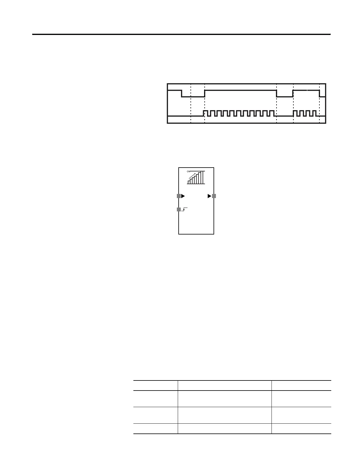
Counter
Counter Function Block Diagram
The counter function block counts the input pulses at an input and
turns on the Output Enable signal when the count reaches a preset
value. You set this value using RSNetWorx for DeviceNet software.
When the input count reaches the preset value, the Output Enable
signal turns on and is held on. To detect pulses in the input signal, the
input pulse’s off-time and on-time must be longer than the controller’s
cycle time. If the input pulse signal off-time and on-time are shorter
than the controller’s cycle time, pulses may be missed.
Counter Function Block Parameters
Set these parameters for the Counter function block.
Input 1 (NO)
Output Enable
Idle to Run
Counter Function Block Parameters
Parameter Valid Range Default Setting
Reset condition Auto reset
Manual reset
Manual reset
Count type Down counter (decrementing)
Up counter (incrementing)
Down counter
(decrementing)
Counter 1…65,535 counts 1 count
Input
Output Enable
Reset

 Loading...


