Publication 1752-UM001A-EN-P - October 2006
Function Blocks Command Reference 201
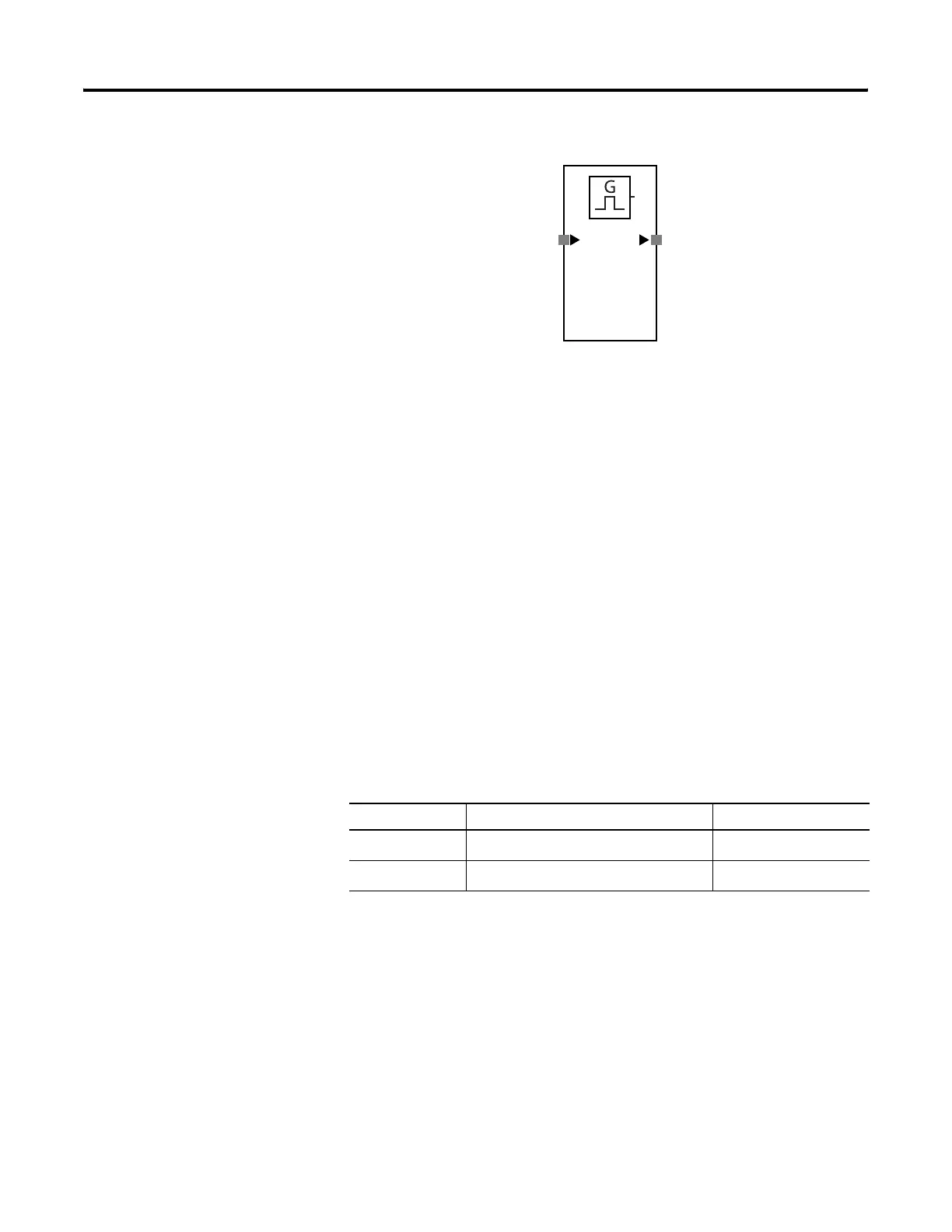
Pulse Generator
Pulse Generator Function Block Diagram
The Pulse Generator function block generates an On/Off pulse output
at the output enable signal while the function block’s input signal is
on.
The pulse’s on-time and off-time can be set independently between
10 ms and 3 seconds in 10 ms increments. When the on-time is set to
100 ms and the off-time is set to 500 ms, the signal will be repeatedly
turned on for 100 ms and then off for 500 ms.
The output pulse width will have a timing error equivalent to the
cycle time of the SmartGuard controller. For example, if the
SmartGuard controller’s cycle time is 7 ms and the pulse width is set
to 100 ms, the output pulse will be anywhere between 93 and 107 ms.
Pulse Generator Function Block Parameters
Set these parameters for the Pulse Generator function block.
Pulse Generator Function Block Parameters
Parameter Valid Range Default Setting
On pulse time
10 ms…3 s in 10 ms increments
(1)
(1) The set value must be longer than the controller’s cycle time.
500 ms
Off pulse time
10 ms…3 s in 10 ms increments
(1)
500 ms
Input
Output Enable
On Pulse Time:
500 ms

 Loading...


