Publication 1752-UM001A-EN-P - October 2006
176 Function Blocks Command Reference
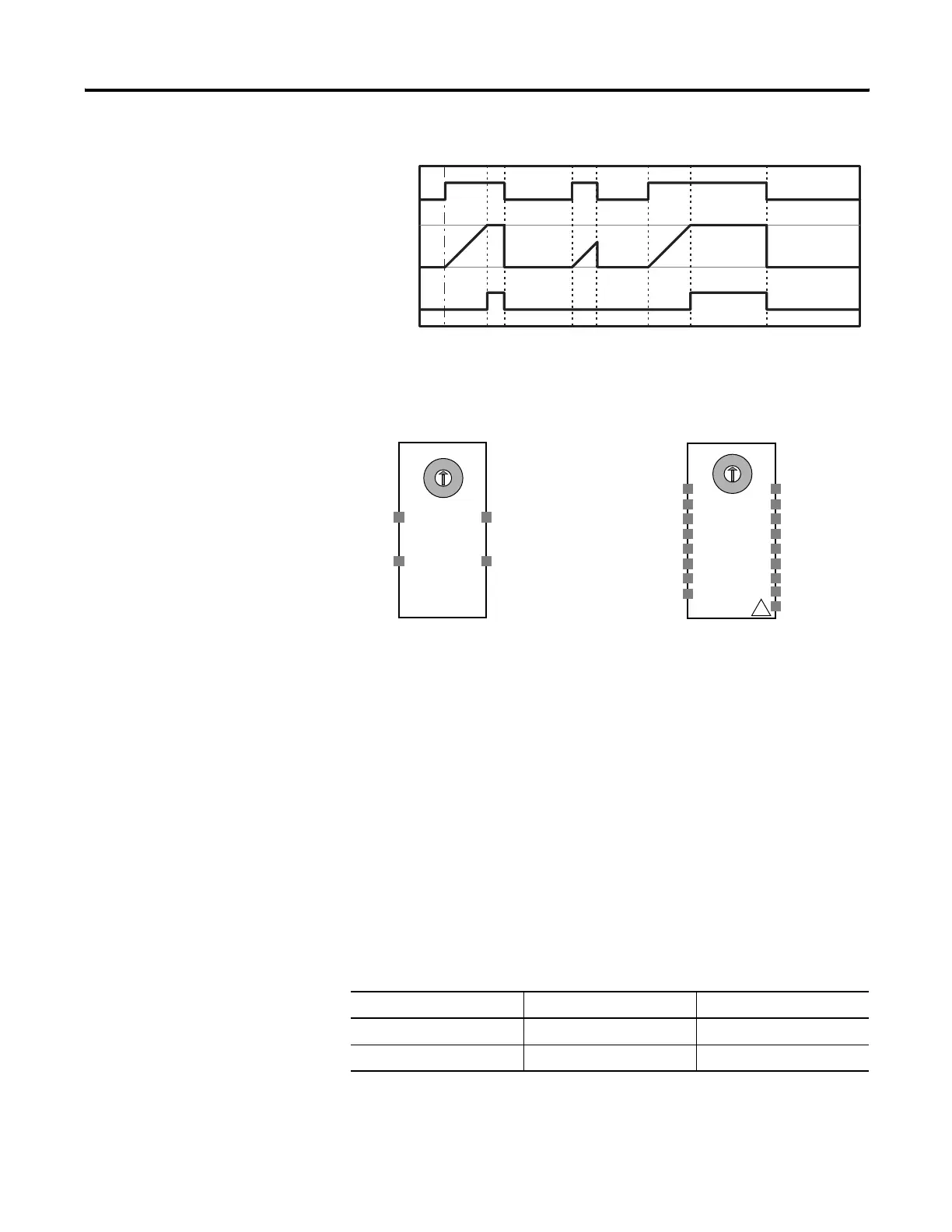
ON-Delay Timer Function Block Timing Chart
User Mode Switch Function
Block
User Mode Switch Function Block Diagram
The User Mode Switch function block is used to monitor an operating
mode switch in the user system or device. The operating mode switch
that can be connected with this function block must be a 1-of-N type
switch, that is, one of the N contacts is ON. The function block
supports a maximum of eight inputs and eight corresponding outputs.
User Mode Switch Function Block Optional Outputs
The number of I/O can be increased on the In/Out Settings tab of the
Function Block Properties dialog.
Set these parameters for the optional outputs.
Input
Idle to Run
Output
Enable
Set Value
Timer
Value 0
User Mode Switch Optional Output Parameters
Parameter Range Default
Number of Inputs 2…8 2
Number of Outputs 2…8 2
1
2
3
4
5
6
7
8
1
2
3
4
5
6
7
8
!
Input 1
Output 1
Input 2
Output 2
Input 1
Output 1
Input 2
Output 2
Input 3
Output 3
Input 4
Output 4
Input 5
Output 5
Input 6
Output 7
Input 7
Output 8
Input 8
Fault Present
Output 6
Default Connections
Maximum Inputs for User Mode Switch Function

 Loading...


