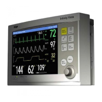
ST Segment Analysis
VF4 Infinity Gamma Series Page 10-5
Isoelectric and ST Measuring Points
ST segment deviations are specified in terms of a displacement
above or below the isoelectric level. To calculate this displace-
ment, the monitor compares the amplitudes of the signal at two
user-selectable measurement points in the patient’s QRS wave-
form. One point is typically set at the isoelectric level on the
waveform. The other point is typically set within the ST segment
of the waveform. The difference (in millimeters or millivolts)
between the amplitude of the isoelectric point and the amplitude
of the ST measurement point represents the ST deviation. The
available settings for each point are:
! Isoelectric Point: from the start of the averaged ST complex
to the Fiducial point, in increments of 4 ms
! ST Measurement Point: from the Fiducial point to the end of
the averaged ST complex, in increments of 4 ms
The default position for the isoelectric point is -28 milliseconds
before the start of the QRS complex, as measured along the hori-
zontal (time) axis. The default position for the ST measurement
point is +80 milliseconds after the end of the QRS complex. The
starting and ending points for the QRS complex are determined
by the QRS detection algorithm.
In practice, however, the determination of the isoelectric and ST
measurement points must be made on the basis of a careful clini-
cal evaluation. The ST display provides the means for changing
the isoelectric and ST measurement points in order to ensure an
accurate ST deviation measurement.
NOTE: You should always check the position of the isoelectric
and ST measurement points before starting ST monitoring.

 Loading...