GE DRAFT VOLUSON™ P8/VOLUSON™P6
DIRECTION 5775469, R
EVISION 3 DRAFT (JULY 19, 2018) BASIC SERVICE MANUAL
Chapter 8 - Replacement Procedures 8-131
8-42-5 Installation Procedure
8-42-5-1 DRFG (5786027) Installation Procedure
1.) Install the new parts in the reverse order of removal.
2.) Perform 8-42-6 Serial Number - Reprogamming Procedure to reprogram the serial number.
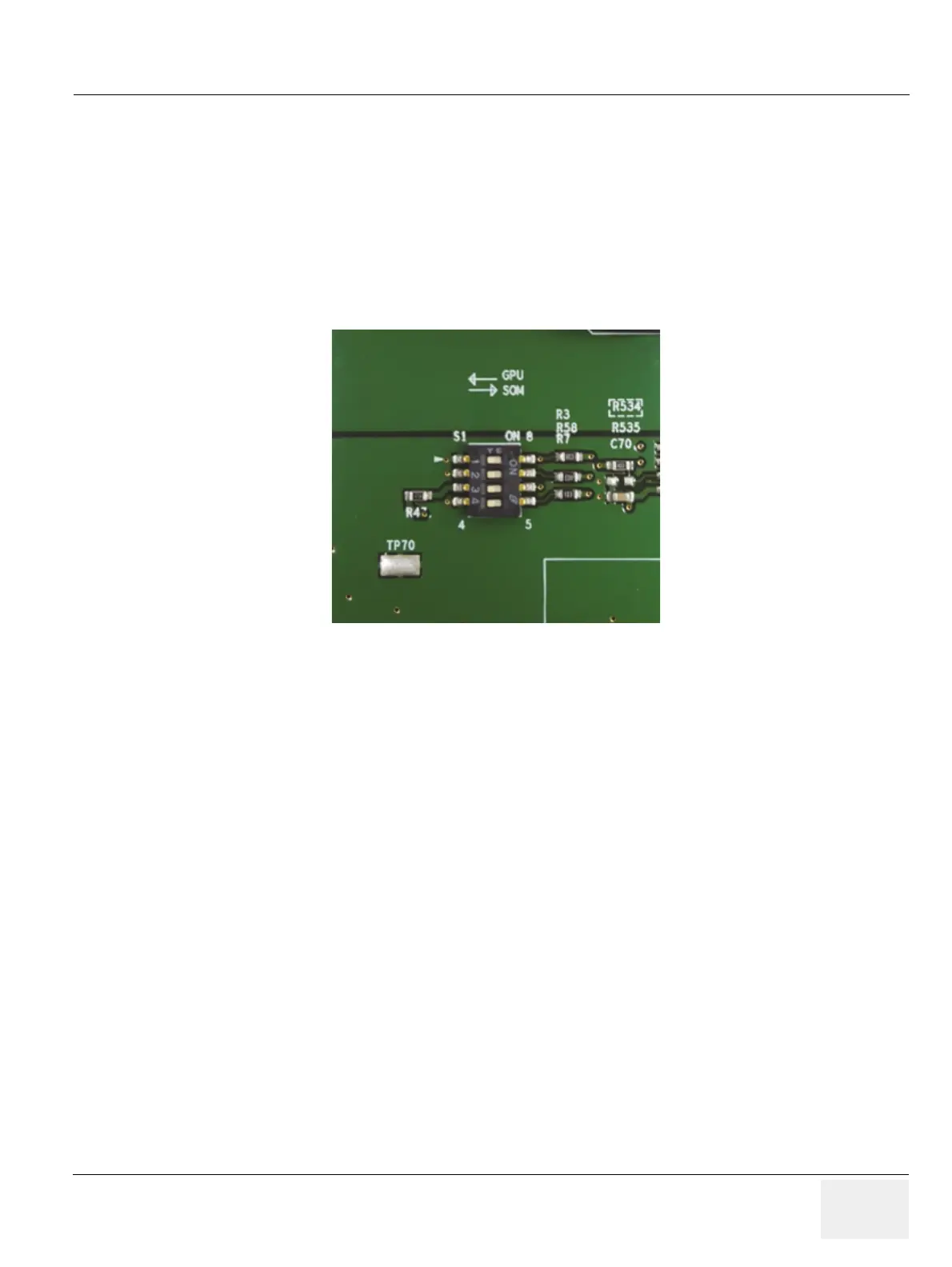
NOTE: Check S1. if GPU is mounted, PIN number 1,2,3,4 of the switch should be located in left.
-If GPU is not mounted, PIN number 1,2,3,4 of the swtich should be located in right.
Figure 8-190 Location of 4 pin of switch
 Loading...


