Home
Honeywell
Network Hardware
HPM
Honeywell HPM User Manual
5
of 1
of 1 rating
498 pages
Give review
Manual
Specs
To Next Page
To Next Page
To Previous Page
To Previous Page
Loading...
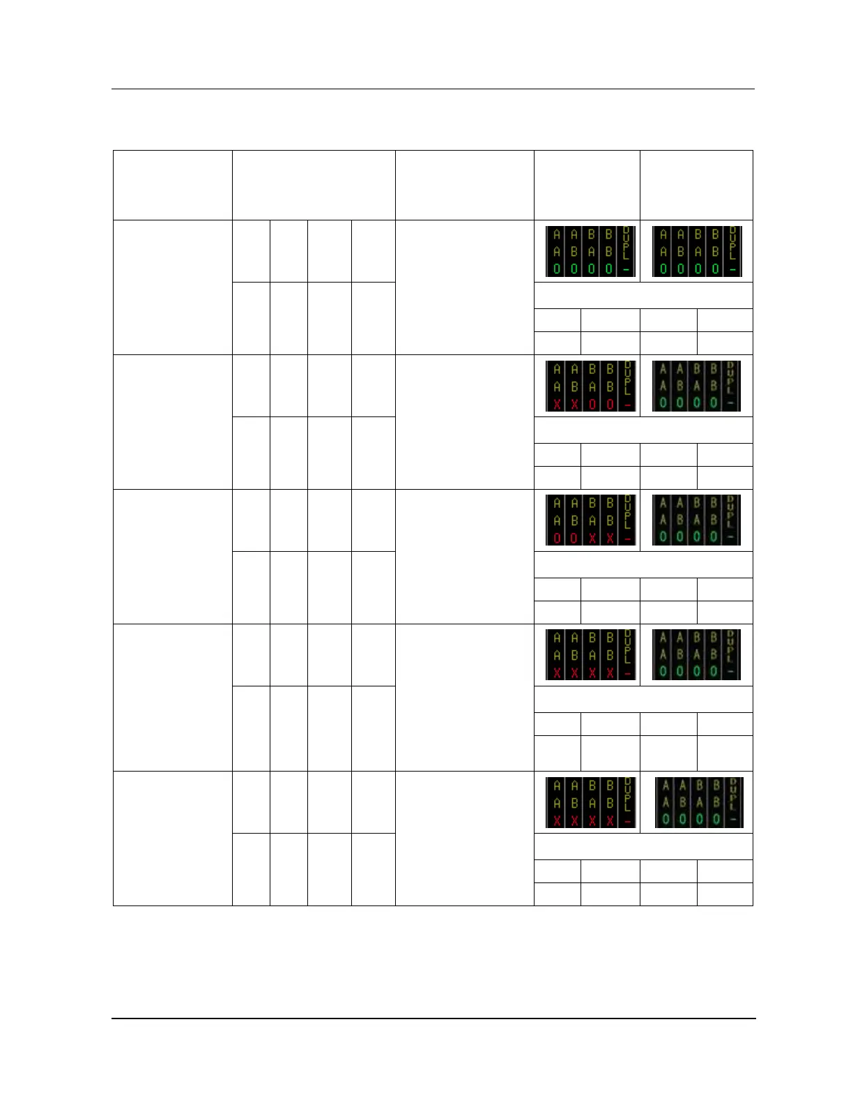
2 Equipment Description
2.27 EUCN Cable System
R688
HPM High-Performance Process Manager Service
151
December 2020
Honeywell
Table
17
EHPM
Cable
Fa
ults
Error scenario
UCN COMM STATUS
UCN CABLE
STATUS/FTE
CABLE STATUS
$FTESTS2
displays
(EHPM with
cable faults)
$FTESTS2
displays
(all other EUCN
nodes)
No FTE cable
problems
A
SIL
B
SIL
A
NSY
B
NSY
OK/OK
UCN: OK/BACKUP
LCN: OK/BACKUP
FTE
co
mposite status
A-
>A
A-
>B
B-
>A
B-
>B
OK
OK
OK
OK
If FTE cable A on
an EHPM node
has a problem
A
SIL
B
SIL
A
NSY
B
NSY
FAIL/FAIL
UCN: OK/BACKUP
LCN: OK/BACKUP
*
FTE composite status
A-
>A
A-
>B
B-
>A
B-
>B
SIL
SIL
OK
OK
I
f
FTE cable B on
an EHPM node
has a problem
A
SIL
B
SIL
A
NSY
B
NSY
FAIL/FAIL
UCN: OK/BACKUP
LCN: OK/BACKUP
*
FTE composite status
A-
>A
A-
>B
B-
>A
B-
>B
OK
OK
SIL
SIL
If both FTE cable
A and FTE cable
B on a Primary
EHPM node have
a pr
oblem
Primary fails,
Secondary takes
over as the
primary
A
SIL
B
SIL
A
NSY
B
NSY
OK/OK
UCN:
PARTFAIL/OFFNET
LCN: OK/BACKUP
*
[1]
*
[1]
FTE composite status
A-
>A
A-
>B
B-
>A
B-
>B
OK
OK
OK
OK
If both FTE cable
A and FTE cable
B on
a
Sec
on
dary
EHPM node have
a problem
A
SIL
B
SIL
A
NSY
B
NSY
OK/OK
UCN:
PARTFAIL/OFFNET
LCN: OK/BACKUP
*
[1]
*
[1]
FTE composite status
A-
>A
A-
>B
B-
>A
B-
>B
OK
OK
OK
OK
[1]
Not
e:
The A SIL, B SIL, A NSY, and B NSY indicatio
ns only app
ear fo
r
an instant and then s
hows
blank due to node failure or
loss of communication.
Note:
If any SIL or
NSY bits are set, then the corr
esponding cables are
backlit on the UCN Status
Display, if the UCN C
ABLE STATUS target is chose
n.
150
152
Table of Contents
Table of Contents
9
Introduction
29
Overview
29
Purpose of this Manual
29
Service Philosophy
29
Equipment Description
31
Overview
31
Introduction
31
Component Part Numbers
31
Power System Controls
31
Power Supply Module Control
31
HPMM/IOP Card Power Interrupt Switches
31
HPM Subsystem Overview
32
Major Assemblies
32
Card File Types
32
Card File Designations
33
Nonredundant 15-Slot HPMM Card File
33
Redundant 15-Slot HPMM Card Files
33
Nonredundant 7-Slot HPMM Card File
33
Redundant 7-Slot HPMM Card Files
33
Nonredundant HPMM Cabinet Layout
34
Figure 1 Cabinet Layout - HPM with Nonredundant HPMM
34
HPMM and IOP Card Files
35
Introduction
35
HPMM and IOP Card File Differences
35
Non-CE Compliant Card File Models
35
CE Compliant Card File Models
35
Conversion Kit
35
HPMM Card Files
35
Table 1 Card File Models
35
HPMM Card File Configurations
36
15-Slot HPMM Card File
37
Figure 2 15-Slot HPMM Card File
37
HPMM Functionality
38
HPMM Card/Module Types
38
Card/Module Illustrations
38
Table 2 HPMM Card/Module Types
38
Power Indicators
39
Status Indicators
39
Diagnostic Display
39
Diagnostic Display Analysis Example
40
Detailed Diagnostic Display Switch
40
Debug Connector
40
HPMM +5 Volt Power Margins
41
HPM UCN Interface Module Illustration
41
Figure 3 HPM UCN Interface Module (Front Panel)
41
High-Performance Comm/Control Card
42
Figure 4 High-Performance Comm/Control Card (Front Panel)
42
High-Performance I/O Link Card
43
Figure 5 High-Performance I/O Link Card (Front Panel)
43
EHPM Card Files
44
Introduction
44
EHPM Card File Configurations
44
15-Slot EHPM Card File
45
EHPM Functionality
46
EHPM Card/Module Types
46
Card/Module Illustrations
47
Power Indicators
47
Status Indicators
47
Diagnostic Display
47
Diagnostic Display Analysis Example
48
Detailed Diagnostic Display Switch
48
Debug Connector
48
EHPM +5 Volt Power Margins
49
EHPM FTE Interface Module
49
CF9 Ethernet Switch
50
Enhanced High-Performance Comm/Control Card
50
EHPM Front Panel LED Display Information
51
Service Failed EHPM Cards Flashed with Experion-Integrated Firmware
52
Overview
52
EHPM Comm/Ctrl Card Replacement Procedure
52
IOP Card Files
55
Introduction
55
Total Number of Card Files
55
Remote Card File Installation
55
Total Number of Iops
55
15-Slot IOP Card File
56
Figure 6 15-Slot IOP Card File
56
Types of Input/Output Processors (Iops)
57
AO and DO Iops
57
Redundant Iops
57
Redundant HLAI Iops
58
Figure 7HLAI FTA with Redundant HLAI Iops
58
Redundant AO Iops
59
Figure 8 Analog Output FTA with Redundant Analog Output Iops
59
Low Level Multiplexer IOP (Llmux)
60
Figure 9 Low Level Multiplexer Interconnections
60
Field Termination Assemblies for IOP
61
Two Types of Ftas
61
Power Adapter
61
Remote Hardened Low Level Multiplexer IOP (RHMUX)
61
RHMUX Thermocouple FTA
62
FTA and Power Adapter Installation
62
Figure 10 Remote Hardened Low Level Multiplexer Interconnections
62
IOP to Power Adapter Connection
63
Power Adapter to FTA Connection
63
Power Adapter Indicators
63
Serial Device Interface IOP (SDI)
63
Introduction
63
SDI Interface Configuration
64
Figure 11 Serial Device Interface Interconnections
64
EIA-232 and EIA--422/485 Interfaces
65
EIA-232 Interface Cable Length
65
EIA-422/485 Cable Length Limitation
65
Power Adapter Installation
65
SDI FTA Installation
65
FTA to Power Adapter Interface
65
Model MU-TSDT02 FTA
65
Model MU-TSDM02 FTA
65
Model MU-TSDU02 FTA
65
Cabling Information
65
Serial Interface IOP (SI)
66
Introduction
66
EIA-232 and EIA-422/485 Interfaces
66
Point-To-Point or Multidrop Interfaces
66
EIA Interface Limitations
66
Power Adapter Installation
66
Power Adapter Size
66
New si IOP Slot Summary Display to View Array Points Built on the si FTA
66
Model MU-TSIM12 Interconnections
67
Figure 12 Model MU-TSIM12 Serial Interface FTA Interconnections
67
SI FTA Installation
68
FTA to Power Adapter Interface
68
Cabling Information
68
Model MU-TSIA12 EIA-232 Interface
68
Model MU-TSIM12 EIA-232 Interface
68
Model MU-TSIM22 EIA-422/485 Interface
68
I/O Link Extender (Fiber Optic Link)
69
Introduction
69
See the Following Figures
69
Features and Guidelines
70
Front Panel Indicators
70
Status Indicator Operation
70
Standard I/O Link Extender Connections Nonredundant HPMM
71
Figure 13 Standard I/O Link Extender Interconnections with Nonredundant HPMM
71
Standard I/O Link Extender Connections Redundant Hpmms
72
Figure 14 Standard I/O Link Extender Interconnections with Redundant Hpmms
72
Long Distance I/O Link Extender Connections Nonredundant HPMM
73
Figure 15 Long Distance I/O Link Extender Interconnections with Nonredundant HPMM
73
Long Distance I/O Link Extender Connections Redundant Hpmms
74
Figure 16 Long Distance I/O Link Extender Interconnections with Redundant Hpmms
74
2.13 Field Termination Assembly
75
Terminal Connectors
75
Ftas Types
75
Model and Part Numbers
75
Detailed Descriptions
75
Standard Ftas
75
Table 3 Standard Field Termination Assembly Types
75
Galvanically Isolated Ftas
77
Three Physical Sizes
77
Table 4 Galvanically Isolated Field Termination Assembly Types
77
FTA Mounting Channels
78
Figure 17 Field Termination Assembly (FTA) Sizes
78
Vertical Orientation
79
Horizontal Orientation
79
Typical Cabinet Layout
80
Figure 18 Typical Vertical FTA Mounting Channel Layout
80
Compression or Screw Terminals Available
81
FTA Compression-Type Terminal Connector
81
Figure 19 Typical FTA Compression Terminal Connector
81
FTA Fixed Screw Terminal Connector
82
FTA Removable Screw-Type Connector
82
Figure 20 Typical FTA Fixed Screw Terminal Connector
82
Figure 21 Typical FTA Removable Screw Terminal Connector
82
Galvanic Isolation Module Connectors
83
Crimp Pin-Type Terminal Connector
83
Figure 22 Crimp-Type Galvanic Isolation Module Terminal Connector
83
Compression-Type Terminal Connector
84
Figure 23 Compression-Type Galvanic Isolation Module Terminal Connector
84
2.14 FTA Mounting Channels
85
Introduction
85
Location
85
Number of FTA Mounting Channels
85
Vertical FTA Mounting Channels
85
Horizontal FTA Mounting Channels
85
Dual Access Cabinet Installation
86
Figure 24 Vertical FTA Mounting Channel Installation - Dual Access Cabinet
86
Figure 25 Vertical FTA Mounting Channel Installation - CF9 Mounting
87
Single Access Cabinet Installation
88
Figure 26 Vertical FTA Mounting Channel Installation - Single Access Cabinet
88
2.15 Power Systems
89
Power System Features
89
Standard Power System
89
48 Volt Battery Backup Time Duration
89
CMOS Backup Time Duration
90
PSM Redundancy Requirements
90
Early Production Standard Power System
91
Figure 27 Standard Power System
91
HPM Standard Power System
92
Figure 28 HPM Standard Power System
92
AC Only Power System
93
Figure 29 AC Only Power System
93
2.16 Power Distribution
94
Overview
94
AC Only Power System Ac Power
94
Battery Backup Module
94
Figure 30 Power Distribution
94
48 Volt Battery Switch
95
No Battery Backup (Early Production Standard Power System)
95
Figure 31 Standard Power System Backpanel (Early Production)
95
No Battery Backup (HPM Standard Power System)
96
CMOS Battery Backup
96
Figure 32 HPM Standard Power System Backpanel
96
Standard Power System (Early Production)
97
Figure 33 CMOS Battery Backup Assembly (Early Production)
97
HPM Standard Power System
98
AC Only Power System
98
Figure 34 CMOS Battery Backup Assembly (HPM Standard Power System)
98
2.17 24 VDC Power Distribution
99
Dual Power Distribution Cables
99
Standard Power System
99
AC Only Power System
99
Typical Cabinet Power Distribution
99
Figure 35 Typical Cabinet 24 VDC Power Distribution
99
2.18 Cabinet Fan Assembly
100
Introduction
100
Up to Four Cabinet Fan Assemblies
100
Optional Cabinet Fan Assembly
100
2.19 LLAI Line Frequency Clock Voltage
100
Standard Power System
100
AC Only Power System
100
2.20 24 VDC Fuse Protection
101
Card File Fusing
101
Fuse Removal
101
Fuse Extraction
101
Fuse Insertion
102
Left 7-Slot Card File
102
Left 7-Slot Card File Fuse Protection
102
Table 5 Left 7-Slot Card File Fuse Protection
102
Left 7-Slot HPMM Card File 24 VDC Distribution
103
Figure 36 Left 7-Slot HPMM Card File Backpanel 24 VDC Distribution
103
Left 7-Slot IOP Card File 24 VDC Distribution
104
Figure 37 Left 7-Slot IOP Card File Backpanel 24 VDC Distribution
104
Left 7-Slot Card File Backpanel Fuse Locations
105
Figure 38 Left 7-Slot Card File Backpanel Fuse Locations
105
Figure 39 Left 7-Slot Card File Backpanel Fuse Locations for EHPM
105
Right 7-Slot Card File
106
Right 7-Slot Card File Backpanel Fuse Protection
106
Table 6 Right 7-Slot Card File Backpanel Fuse Protection
106
Right 7-Slot HPMM Card File 24 VDC Distribution
107
Figure 40 Right 7-Slot HPMM Card File Backpanel 24 VDC Distribution
107
Right 7-Slot IOP Card File 24 VDC Distribution
108
Figure 41 Right 7-Slot IOP Card File Backpanel 24 VDC Distribution
108
Right 7-Slot Card File Backpanel Fuse Locations
109
Figure 42 Right 7-Slot Card File Backpanel Fuse Locations
109
Figure 43 Right 7-Slot Card File Backpanel Fuse Locations for EHPM
109
15-Slot Card File
110
15-Slot Card File Backpanel Fuse Protection
110
Table 7 15-Slot Card File Backpanel Fuse Protection
110
15-Slot HPMM Card File 24 VDC Distribution
111
Figure 44 15-Slot HPMM Card File Backpanel 24 VDC Distribution
111
15-Slot IOP Card File 24 VDC Distribution
112
Figure 45 15-Slot IOP Card File Backpanel 24 VDC Distribution
112
15-Slot Card File Backpanel Fuse Locations
113
Figure 46 15-Slot Card File Backpanel Fuse Locations
113
Figure 47 15-Slot Card File Backpanel Fuse Locations
113
IOP Only Card File
114
IOP Only Card File Assemblies
114
IOP Only Card File Fuse Protection
115
Table 8 IOP Only Card File Fuse Protection
115
IOP Only Card File 24 VDC Power Distribution
116
IOP Only Card File Backpanel Fuse Locations
116
Figure 48 IOP Only Card File Backpanel 24 VDC Power Distribution
116
FTA Fuse Protection
117
Figure 49 IOP Only Card File Backpanel Fuse Locations
117
Cabinet Fan Assembly Fuse Protection
118
2.21 5 VDC Fuse Protection
118
High-Performance I/O Link Card
118
HPMM Power Routing and Fuses
119
Figure 50 HPMM Power Routing and Fuses
119
2.22 Card File Power Cabling
120
Card File Power Connectors
120
Power Distribution Assemblies
120
Power System Power Connectors
120
Power Distribution Examples
120
Power Distribution Methods
120
Table 9 Card File Power Cabling
120
15-Slot Card File with Power Distribution Assemblies
121
Figure 51 15-Slot Card File with Power Distribution Assemblies
121
Two 15-Slot Card Files with Power Distribution Assemblies
122
Figure 52 Two 15-Slot Card Files with Power Distribution Assemblies
122
Three 15-Slot Card Files
123
Figure 53 Three 15-Slot Card Files
123
Three 15-Slot Card Files with Power Distribution Assemblies
124
Power Distribution Assemblies for Redundant Cabling
124
Figure 54 Three 15-Slot Card Files with Power Distribution Assemblies
124
2.23 I/O Link Interface Cabling
125
Introduction
125
Table 10 I/O Link Interface Cabling Card File Connector Assignments
125
Figure 55 Power Distribution Assemblies for Redundant Cabling
125
Cable Length
126
Redundant Cables
126
No Cable Termination
126
I/O Link Interface Cabling - Three Card Files
127
Figure 56 Three Card Files
127
I/O Link Interface - Four Card Files
128
Figure 57 Four Card Files
128
I/O Link Interface Cables in Adjacent Cabinets
129
I/O Link Interface Cable Shield Grounding (Non-CE Compliance)
129
I/O Link Interface Cable Shield Grounding (CE Compliance)
129
Induced Power Surge Protection
129
New and Upgraded Subsystems Only
130
Surge Protection Network Power Cables
131
I/O Link Cable Connection
131
Figure 58 Surge Protection Network Power Cables
131
Typical I/O Link and Power Cable Connection
132
Figure 59 I/O Link Interface Cable Connection to Power Cable
132
Figure 60 Typical Cabinet Surge Protection Network Cable Connections
132
Power Cable I/O Link Protector Adapters
134
Figure 61 Power Cable I/O Link Protector Adapters
134
2.24 IOP to FTA Cabling
135
Introduction
135
Standard Ftas
135
Galvanically Isolated Ftas
135
External Cabinet Installation
135
Typical Cable Routing
136
Figure 62 IOP to FTA Cabinet Cabling
136
2.25 Power Adapter Cabling
137
Introduction
137
Llmux Interconnections
137
Figure 63 Power Adapter Interconnections - Llmux Application
137
SDI Interconnections
138
SI Interconnections
138
Figure 64 Power Adapter Interconnections - SDI Application
138
2.26 UCN Cable System
139
Introduction
139
Figure 65 Power Adapter Interconnections - si Application
139
Figure 66 Universal Control Network (UCN) Components
139
Redundant UCN Cables
140
Cable Tap Types
141
Cable Tap Usage
141
Figure 67 UCN Taps
141
Isolated Port Identification
142
Card File Backpanel Connections
142
2.27 EUCN Cable System
142
Introduction
142
Figure 68 UCN Drop Cable Connections to a 7-Slot HPMM Card File
142
Figure 69 Enhanced Universal Control Network (EUCN) Components
143
Redundant EUCN FTE Cables
144
FTESTS Cable Error Scenarios
144
Table 11 EHPM Cable Faults
144
Table 12 ENIM Cable Faults
144
Table 13 Crossover Cable Faults
146
Table 14 EUCN Crossed Cable Faults
146
Cable Troubleshooting Guidelines for EUCN
147
Table 15 ENB Network Topology Terminology
148
Figure 70: ENB Network Topology Example
148
Table 16 ENB Cable Faults
149
Table 17 EHPM Cable Faults
151
Table 18 UCN Node (PM/APM/HPM) Cable Faults (Primary NIM Node Is an ENB)
152
Table 19 UCN Node (PM/APM/HPM) Cable Faults (Primary NIM Node Is a NIM)
153
Table 20 CF9 Switch/Uplink Port Failure
154
Table 21 ES-T/ESVT FTE Cable Faults
154
Diagnosing Complex EUCN FTE Network Faults
155
Table 22 Crossover Cable Faults
155
Figure 71 $FTESTS2 View - EST05 Has Cable a Fault
156
Figure 72 FTE Status from View of EST05 - EST05 Has Cable a Fault
156
Figure 73 UCN Status for L1 Switch a down and CF9 B Downlink Fault
157
Figure 74 $FTESTS for L1 Switch a down and CF9 B Downlink Fault
157
EUCN Switches
158
Card File Backpanel Connections
158
Figure 75 Control Firewall (CF9)
158
Figure 76 Ethernet Switch
158
Status Indicators on the FTE Switch
159
Figure 77 Drop Cable Connections to a 7-Slot HPMM Card File for EHPM
159
Control Firewall Status Indicators
162
2.28 UCN Node Address Pinning
164
Introduction
164
One or Two HPMM Card Files
164
Odd Address Pinning
164
Secondary HPMM Determination
164
Two Methods of Pinning
164
7-Slot Card File Pinning
165
Figure 78 Left 7-Slot Card File UCN Node Address Pinning
165
15-Slot Card File Pinning
166
Two Pinning Methods
166
Pinning Method Differences
166
Figure 79 15-Slot Card File UCN Node Address Pinning
166
Odd Number of Jumpers Required
167
Plug Jumper Method
167
Figure 80 UCN Node Address Pinning Using Plug Jumpers
167
Zero-Ohm Jumper Method
168
Figure 81 UCN Node Address Pinning Using Zero-Ohm Resistors
168
FTE Device Index Addressing
169
Figure 82 - EHPM FTE Interface Module
169
2.29 I/O Link Interface Address Pinning
170
Introduction
170
I/O Link Interface Configuration
170
Consecutive Address Assignment
170
Two Methods of Pinning
170
Nonredundant HPMM Subsystem
171
7-Slot Card Files
171
Figure 83 Left 7-Slot Card File I/O Link Interface Address Pinning
171
15-Slot Card File Redundant HPMM Subsystem
172
7-Slot Card File Redundant HPM Subsystem
172
Figure 84 15-Slot Card File I/O Link Interface Address Pinning
172
IOP Only Card File Pinning Location
173
Two Pinning Methods
173
One Method Only
173
Figure 85 IOP Only Card File I/O Link Interface Address Pinning
173
Jumper Method Example
174
Figure 86 Left 7-Slot Card File I/O Link Interface Address Pinning with Plug Jumpers
174
Zero-Ohm Resistor Jumper Pinning Example
175
Figure 87 Left 7-Slot Card File I/O Link Interface Address Pinning with Zero-Ohm Resistors
175
2.30 Firmware/Hardware/Software Correlation
176
Relationship
176
Ucn Status Displays
179
Overview
179
Introduction
179
References
179
Release 600 Software Displays
179
Display Definitions
179
IOM Definition
179
Target Selection
179
NIM Detail Status Displays
179
HPMM Detail Status Displays
180
IOP Detail Status Displays
180
Detail Status Display Selection Procedures
180
Introduction
180
NIM Detail Status Display Procedure
180
System Status Display
181
Figure 88 System Status Display
181
UCN Status Display
182
Figure 89 UCN Status Display
182
Figure 90 UCN Status Display - EHPM/ENIM
182
NIM Detail Status Display
184
Figure 91 NIM Detail Status Display
184
HPMM Detail Status Display Procedure
185
HPM Status Display
185
Figure 92 HPM Status Display
185
Figure 93 HPM Status Display - EHPM
186
Primary HPMM Detail Status Display
187
Figure 94 Primary HPMM Detail Status Display
187
Secondary HPMM Detail Status Display
188
Figure 95 Secondary HPMM Detail Status Display
188
IOP Detail Status Display Procedure
189
IOP Detail Status Display
189
Figure 96 IOP Detail Status Display
189
Display Operation
190
Introduction
190
UCN Status Displays
190
Figure 97 UCN Status Display
190
Three Display Sections
191
Device Status
191
Table 23 UCN Status Display - UCN/NIM Status
191
Auxillary Status
192
Selecting the Status Box Target
192
Primary HPMM Status
192
Table 24 UCN Status Display - Primary HPMM Status
192
Secondary HPMM Status
193
Table 25 UCN Status Display - Secondary HPMM Status
193
LOAD/SAVE RESTORE Target
194
Figure 98 UCN Status Display - LOAD/SAVE RESTORE Target Selected
194
Table 26 UCN Status Display - LOAD/SAVE RESTORE
195
CONTROL STATES Target
196
Figure 99 UCN Status Display - CONTROL STATES Target Selected
196
Table 27 UCN Status Display - CONTROL STATES Target Selected
197
AUTO CHECKPT Target
198
Figure 100 UCN Status Display - AUTO CHECKPT Target Selected
198
Table 28 UCN Status Display - AUTO CHECKPT Target Selected
199
UCN CABLE STATUS Target
200
Figure 101 UCN Status Display - UCN CABLE STATUS Target Selected
200
Figure 102 UCN Status Display - NIM Node and UCN CABLE STATUS Targets Selected
201
Figure 103 UCN Status Display - HPM Node and UCN CABLE STATUS Targets Selected
201
Table 29 UCN CABLE STATUS Target Selected
202
Figure 104 UCN Network Statistics Display
204
Figure 105 UCN Network Statistics Display - UCN Node Selected
204
Table 30 UCN Network Statistics Display Definitions
205
Table 31 EUCN Network Statistics Display Definitions
206
RUN STATES Target
207
Figure 106 UCN Status Display - RUN STATES Target Selected
207
Table 32 UCN Status Display - RUN STATES Target Selected
208
SLOT SUMMARY Target
209
Figure 107 UCN Status Display - SLOT SUMMARY Target Selected
209
Figure 108 UCN Status Display - REGULATORY CONTROL POINTS Target Selected
210
DETAIL STATUS Target
211
System Error Journal Messages
211
HPM Status Displays
211
Introduction
211
Figure 109 HPM Status Display
211
Primary and Secondary Hpmms
212
Table 33 HPM Status Display - UCN and HPM Status
212
HPMM Node Number
213
HPMM Operational States
213
Primary HPMM Status
213
Table 34 HPM Status Display - Primary HPMM Status
213
Secondary HPMM Status
214
40 IOP Status Boxes
214
IOP Status Box Definitions
214
IOP Synchronization Status
214
IOP Status States
214
Table 35 HPM Status Display Definitions - Secondary HPMM Status
214
IOP a Status States
215
Table 36 HPM Status Display - IOP a Status
215
IOP B Status States
216
Command Targets
216
Table 37 HPM Status Display - IOP B Status
216
LOAD/SAVE RESTORE Target
217
Figure 110 HPM Status Display - LOAD/SAVE RESTORE Target Selected
217
LOAD/SAVE RESTORE Display Targets
218
Table 38 HPM Status Display - LOAD/SAVE RESTORE Target Selected
218
CONTROL STATES Target
219
CONTROL STATES Display Targets
219
AUTO CHECKPT Target
219
Table 39 HPM Status Display - CONTROL STATES Target Selected
219
Figure 111 HPM Status Display - CONTROL STATES Target Selected
219
AUTO CHECKPT Display Targets
220
Table 40 HPM Status Display - AUTO CHECKPT Target Selected
220
Figure 112 HPM Status Display - AUTO CHECKPT Target Selected
220
IOL CABLE COMMANDS Target
221
Figure 113 HPM Status Display - IOL CABLE COMMANDS
221
IOL CABLE COMMANDS Display Targets
222
Table 41 HPM Status Display - IOL CABLE COMMANDS
222
RUN STATES Target
223
Figure 114 HPM Status Display - RUN STATES Target Selected
223
RUN STATES Display Targets
224
Table 42 HPM Status Display - RUN STATES Target Selected
224
SLOT SUMMARY Target
225
Figure 115 HPM Status Display - SLOT SUMMARY Target Selected
225
REGULATORY CONTROL POINTS Target
226
Process Module Points Display Targets
226
DETAIL STATUS Target
226
Figure 116 HPM Status Display - REGULATORY CONTROL POINTS Target Selected
226
NIM Detail Status Displays
227
Selection Procedure
227
NIM Driver Configuration Display
227
Figure 117 NIM Driver Configuration Display
227
NIM Driver Configuration Display Status
228
UCN Driver Statistics (UCN STATS Target)
228
Table 43 NIM Driver Configuration Display Status
228
NIM and HPMM Display Differences
229
Page Statistical and Status Content
229
Switching Display Pages
229
NIM Local UCN Statistics Display
229
Figure 118 NIM Local UCN Statistics Display
229
NIM Local UCN Statistics Display
230
Two Pages
230
Cable Noise/Silence
230
Time Sync Operation
230
Figure 119 NIM Local UCN Statistics Display
230
Four Second Update
231
HELP Target
231
HPMM Detail Status Displays
232
HPMM Detail Status Display Selection
232
Primary HPMM Detail Status Display
232
Figure 120 Primary HPMM Detail Status Display
232
Secondary HPMM Detail Status Display
233
Targets and Bottom Data Fields
233
Figure 121 Secondary HPMM Detail Status Display
233
Bottom Data Fields Defined
234
Four-Second Update
234
Target Comparison
234
Table 44 HPMM Detail Status Display
234
HPMM I/O Link Information Display
235
Primary HPMM I/O Link Information Display
235
Figure 122 Primary HPMM I/O Link Information Display
235
Secondary HPMM I/O Link Information Display
236
Four -Second Update
236
Figure 123 Secondary HPMM I/O Link Information Display
236
HPMM I/O Link Status
237
Table 45 HPMM I/O Link Information Display
237
HPMM IOM I/O Link Information Display
239
Data Tables
239
Figure 124 IOM I/O Link Information Display
239
DSA Data Fields
240
Table 46 IOM I/O Link Information Display
240
HPMM Version/Revision Display
241
Figure 125 HPMM Version/Revision Display
241
Version and Revision Data
242
Table 47 HPMM Version/Revision Display
242
HPMM Control Configuration Display
243
HPMM Write Lockout Control Display
243
Figure 126 HPMM Write Lockout Control Display
243
Control Configuration Display Information
244
Table 48 HPMM Control Configuration Display
244
Schedule Overrun Counters
245
HPM Write Lockout Displays
245
Table 49 HPMM Schedule Overrun Counters Statistics
245
Figure 127 HPM Write Lockout Target
245
Figure 128 HPM Write Lockout Control Display - Improper US Keylock Position
246
Figure 129 HPM Write Lockout Control Help Display
247
HPMM Schedule Information Display
248
Figure 130 HPMM Schedule Information Display
248
HPMM UCN Statistics Displays
249
Table 50 Performance Statistics
249
Figure 131 HPMM UCN Statistics Display
250
Figure 132 HPMM UCN Statistics Display
250
HPMM Maintenance Support Displays
251
Figure 133 HPMM Communications Error Block Display
252
Figure 134 HPMM Control Block Display
253
Figure 135 HPMM Control Patches Display
254
Figure 136 HPMM Communications Patches Display
255
Figure 137 HPMM Node Status Information Display
256
Table 51 HPMM Node Status Information Display
257
Manufacturing Information Display
258
Figure 138 Manufacturing Information Display
258
HPMM Soft Failure Displays
259
Figure 139 HPMM Soft Failure Display
259
Figure 140 HPMM Soft Failure Display - 00-39
260
Figure 141 HPMM Soft Failure Display - 40-79
260
Figure 142 HPMM Soft Failure Display - 80-95
261
IOP Detail Status Displays
262
Overview
262
Top Portion of Display
262
Primary and Secondary IOP Displays
262
Figure 143 HLAI IOP Detail Status Display
262
Bottom of Display
263
IOP Configuration
263
Table 52 IOP Detail Status Display - IOP Configuration
263
I/O Link Cable Status and Statistics
264
Status Messages
264
Table 53 IOP Detail Status Display - I/O Link Cable Status/Statistics
264
Table 54 IOP Detail Status Display - I/O Link Cable Status Messages
264
Loss of Communications
265
4-Second Data Update
265
IOP Box Soft Failures Displays
265
Figure 144 IOP Box Soft Failures Display
266
Figure 145 IOP Box Soft Failures Display
267
Figure 146 IOP Box Soft Failures Display
267
Figure 147 IOP Box Soft Failures Display
268
Figure 148 IOP Box Soft Failures Display
268
Figure 149 IOP Box Soft Failures Display
269
IOP Slot Soft Failures Displays
270
Figure 150 IOP Slot Soft Failures Display
271
Figure 151 IOP Slot Soft Failures Display
271
Figure 152 IOP Slot Soft Failures Display
271
Figure 153 IOP Slot Soft Failures Display
272
IOP Slots with Soft Failures Display
273
HLAI IOP Detail Status Display
273
Figure 154 IOP Slots with Soft Failures Display
273
Figure 155 High Level Analog Input IOP Detail Status Display - ENABLE CALIBRATN Target Selected
274
LLAI IOP Detail Status Display
275
Figure 156 High Level Analog Input IOP Detail Status Display - DISABLE CALIBRATN Target Selected
275
Figure 157 Low Level Analog Input IOP Detail Status Display -ENABLE CALIBRATN and ENABLE RJ CALIBR Targets
275
Figure 158 Low Level Analog Input IOP Detail Status Display - DISABLE CALIBRATN Target Selected
277
Figure 159 Low Level Analog Input IOP Detail Status Display - DISABLE RJ CALIBR Target Selected
278
Figure 160 Low Level Analog Input IOP Detail Status Display
279
AO IOP Detail Status Display
280
Table 55 Low Level Analog Input IOP Detail Status Display
280
Figure 161 8-Channel -Analog Output IOP Detail Status Display
281
Figure 162 16-Channel Analog Output IOP Detail Status Display
282
Figure 163 Analog Output IOP Detail Status Display - ENABLE CALIBRATN Target Selected
283
Llmux IOP Detail Status Display
284
Figure 164 Analog Output IOP Detail Status Display - DISABLE CALIBRATN Target Selected
284
Figure 165 Low Level Multiplexer IOP Detail Status Display-ENABLE CAL on Target Selected
285
Figure 166 Low Level Multiplexer IOP Detail Status Display-DISABLE CALIBRATN Target Selected
285
RHMUX IOP Detail Status Display
286
Figure 167 Low Level Multiplexer IOP Detail Status Display
286
Figure 168 Remote Hardened Multiplexer IOP Detail Status Display - ENABLE CAL on Target Selected
287
Figure 169 Remote Hardened Multiplexer IOP Detail Status Display - DISABLE CALIBRATN Target Selected
288
DI IOP Detail Status Display
289
Figure 170 Remote Hardened Multiplexer IOP Detail Status Display
289
DO IOP Detail Status Display
290
Figure 171 Digital Input IOP Detail Status Display
290
Figure 172 16-Channel Digital Output IOP Detail Status Display
291
STI/STIM IOP Detail Status Display
292
Figure 173 32-Channel Digital Output IOP Detail Status Display
292
PI IOP Detail Status Display
293
Figure 174 Smart Transmitter Interface IOP Detail Status Display
293
SDI IOP Detail Status Display
294
Figure 175 Pulse Input IOP Detail Status Display
294
SI IOP Detail Status Display
295
Figure 176 Serial Device Interface IOP Detail Status Display
295
DISOE IOP Detail Status Display
296
Figure 177 Serial Interface IOP Detail Status Display
296
Figure 178 Digital Input Sequence of Events IOP Detail Status Display
297
Figure 179 IOP PI Loading Information Display
298
Table 56 IOP PI Loading Information Display
299
Fault Isolation
301
Overview
301
Purpose
301
Release 500 Software Displays
301
Failure Types
301
Two Types of Failures
301
Hard Failure
301
Soft Failure
301
Hard and Soft Failures
301
HPM Failure
301
HPMM Hard Failure
302
HPM Partial Failure
302
HPMM Soft Failure
302
IOP Hard Failure
302
IOP Soft Failure
302
Fault Isolation Concepts
303
Introduction
303
Troubleshooting Flowcharts
303
Recommendations for Operators and Service Technicians
304
Troubleshooting Table Usage
304
Troubleshooting Flow Chart
306
Figure 180 HPM Fault Isolation Flowchart (Sheet 1 of 6)
306
Figure 181 HPM Fault Isolation Flowchart (Sheet 2 of 6)
307
Figure 182 HPM Fault Isolation Flowchart (Sheet 3 of 6)
308
Figure 183 HPM Fault Isolation Flowchart (Sheet 4 of 6)
309
Figure 184 HPM Fault Isolation Flowchart (Sheet 5 of 6)
310
Figure 185 HPM Fault Isolation Flowchart (Sheet 6 of 6)
311
HPMM Corrective Actions
312
Table 57 HPMM Corrective Actions
312
I/O Link Overruns
314
I/O Link Overruns Corrective Actions
315
Comm/Control Hard Failure Codes
315
Table 58 Communications and Control Processor Hard Failure Codes
315
HPMM Soft Failure Codes
335
Comm/Control Soft Failure Error Codes
337
Table 59 Comm/Control Soft Failure Error Codes
337
I/O Link Processor Hard Failure Error Codes
340
Table 60 I/O Link Hard Failure Error Codes
340
IOP Hard Failure Error Codes
341
Table 61 IOP Hard Failure Error Codes
341
IOP Box Soft Failure Error Codes
343
Table 62 IOP Box Soft Failure Error Codes
343
IOP Slot Soft Failure Error Codes
348
Table 63 IOP Slot Soft Failure Error Codes
348
Additional Troubleshooting for EUCN Nodes
349
Smart Transmitter Interface
350
Introduction
350
STI IOP and FTA Faults
350
Two Wire Link or Smart Transmitter Faults
351
FTA Redundancy Indicators
351
Introduction
351
AO FTA Redundancy Indicator
351
HLAI FTA Redundancy Indicator
351
Redundant Analog Output IOP Failure Diagnosis
351
Considerations
352
Avoid Removing IOP a
352
IOP a Preference
352
Replacing the FTA Switching Module
352
Switch to IOP a When a Soft Failure Occurs
352
Consider Use of an AO Standby Manual Device
352
OK/CNF [S] Status
353
Replacing the Switching Module
353
[S] CNF/OK Status
353
Best Solution When Replacing Switching Module
353
Switching Module Replacement Procedure
354
IOP B Should be Secondary
354
Battery Backup Exhaustion
354
Introduction
354
Loss of 24 VDC
354
Multiple Battery Backup
354
US Response to 48 VDC Battery Failure
354
HPMM Card and Module Indicators
355
Application of Power
355
Status Indicators and Alphanumeric Display
355
HPM UCN Interface Module
355
Indicator Functionality
355
Table 64 HPMM Card and Module Indicators
355
High-Performance Comm/Control Card Status Indicator
356
High-Performance I/O Link Card Status Indicator
356
HPM UCN Interface Module Transmit Indicator
357
Power and Status Indicators
357
HPMM Fuse
357
UCN Interface Module Fuse
357
HPMM Card Extractors
357
HPMM Alphanumeric Display
358
Introduction
358
Detailed Display Switch
358
Rapidly Changing of Display Contents
358
Alphanumeric Display Format
358
Table 65 Alphanumeric Display Formats
359
Table 66 EHPM Alphanumeric Display Formats
361
Notification Displays
363
Cold HPMM Startup Display Sequences
363
Table 67 User Notification Message Formats
363
Table 68 Alphanumeric Display for a Normal Startup Sequence
363
Table 69 Alphanumeric Display for Startup/Factory Test Mode Sequence
364
HPMM Load Display Sequence
365
Table 70 Alphanumeric Display for HPMM Cold Startup Failure Sequence
365
Table 71 Alphanumeric Display for Load Sequence
365
Nonredundant HPM Failure Sequences (after Load)
366
Table 72 Communications/I/O Link Processor Failure Display Sequence
366
Table 73 Control Processor Failure Display Sequence
367
HPMM RAM Retention Startup Sequence
368
Table 74 RAM Retention Startup Display Sequence
368
HPMM Redundancy Display Sequences
369
Table 75 Alphanumeric Display for HPMM Swapping Sequence (Detailed Display Mode)
369
Table 76 Alphanumeric Display for HPMM Swapping Sequence (Non-Detailed Display Mode)
370
Table 77 Alphanumeric Display for Failover HPMM Swapping Sequence (Detailed Display Mode)
370
HPMM Alphanumeric Display Blanking
371
Table 78 Alphanumeric Display for Failover HPMM Swapping Sequence (Non-Detailed Display Mode)
371
HPMM Diagnostic Tests List
372
Table 79 HPMM Diagnostic Test List
372
4.10 HPM Alternate Private Path
377
Overview
377
Equipment and Revision Requirements
378
HPPM Redundancy Restoration Procedure
378
4.11 I/O Card Indicators
380
Loss of Power
380
Overview
380
Indicator Functionality
380
Table 80 IOP Card Indicators
380
Multifunctional Status Indicator
381
4.12 FTA Indicators
381
Introduction
381
FTA Indicator Functions
381
Table 81 IOP Multicolor Status Indicator
381
Table 82 FTA Indicators
381
4.13 Power System Indicators
382
Standard Power System
382
Figure 186 Standard Power System Indicators
382
Figure 187 Standard Power System Annunciator Contact Connections
384
AC Only Power System
385
4.14 Power System Voltage Checks
385
Introduction
385
Standard Power System
386
Table 83 Standard Power System Voltage Test Points
386
Figure 188 Power System Power Output Connector Pin Assignments
386
Figure 189 Power Supply Module Test Points and Indicators
387
Figure 190 Power System AC Wiring
387
AC Only Power System
388
Table 84 AC Only Power System Voltage Test Points
388
Ucn Exerciser
391
Overview
391
Purpose
391
Applications
391
Two Part Test
391
Request Data Response (RDR) Test
392
Introduction
392
RDR Protocol
392
Figure 191 RDR Test Configuration
392
Triangulation Test
393
Introduction
393
Timeout Policy
393
Figure 192 Triangulation Test
393
5.5 Test Operation
394
UCN Exerciser Operation
394
Starting the UCN Exerciser
394
PAGE Target
394
HELP Target
394
UCN Exerciser Overview Display
394
Figure 193 UCN Exerciser Overview Display
394
Figure 194 UCN Exerciser Overview Display
394
UCN Exerciser Help Display
395
Connection Test Summary Display
395
Figure 195 UCN Exerciser Help Display
395
Figure 196 Connection Test Summary Display
395
Connection Test Summary Display
397
UCN Exerciser Test Procedure
397
Figure 197 Connect Test Summary Display
397
Analyzing Results
399
Connect Test Detail Display
399
Number of Attempt Errors
399
Problem Correction
399
Figure 198 Connection Test Detail Display
399
Removal and Replacement
401
Overview
401
Introduction
401
Electrostatic Discharge Protection
401
ESD Guidelines for HPMM and IOP Cards
402
Static Discharge Effects
402
ESD Kit
402
Building a Static Discharge Probe
402
Figure 199 Cabinet ESD Wriststrap Connection
402
ESD Prevention Rules
403
HPMM and IOP Cards
404
Removal and Replacement
404
HPMM and IOP Card Removal and Replacement
404
HPM UCN Interface Module Removal and Replacement
404
Tightening the Knurled Screw
405
HPM UCN Interface Module
405
Figure 200 HPM UCN Interface Module Installation
405
EHPM FTE Module Installation
406
Standby Manual Device Overview
407
Introduction
407
No External Power Source Option
407
Standby Manual Device Connections
407
DO Standby Manual Device Connection
408
Figure 201 Digital Output Manual Device Interconnection
408
Device Interchangeability
409
DIN to Phone Connector Adaptor Cable
409
Board Revision Level
409
AO Standby Manual Device Operation
409
Purpose
409
Two Models
409
Original Analog Output Standby Manual Device
410
Figure 202 Original Analog Output Standby Manual Device (Two Per Device)
410
Compact Analog Output Standby Manual Device
412
Figure 203 Compact Analog Output Standby Manual Device
412
DO Standby Manual Device Operation
414
Purpose
414
Secondary Function
414
Mounting Locations
414
Connection
415
Output Control Switches Disablement
415
Switch Activation
415
Figure 204 Model MU-SMDC02 Portable Digital Output Standby Manual Device
415
Standby Manual Device Control Procedure
416
Figure 205 Digital Standby Manual Device Panel
416
Normal IOP Control Procedure
418
HPMM or IOP Card Case Replacement
419
Handling and Installing HPM Components
419
Disassembly/Assembly Procedure
419
Card Case Illustration
420
Figure 206 Replacing HPMM or IOP Card Case
420
IOP to FTA Cable Replacement
421
Nonredundant IOP Cable Replacement
421
Redundant IOP Cable Replacement
421
FTA Replacement
421
Replacement Procedure
423
FTA Module and Relay Replacement
424
Replacement Procedure
424
LLAI Module Replacement
424
AO Redundancy Switching Module Replacement
424
SDI/SI Module and Fuse Replacement
424
Galvanic Isolation Module Replacement
424
6.10 Card File Replacement
425
Replacement Procedure
425
6.11 Power System
425
Introduction
425
6.12 CMOS Battery Replacement
425
Nicad Batteries
425
Alkaline Batteries
426
Replacement Procedure
426
6.13 48 V Backup Battery Replacement
426
Battery Operational and Service Life
426
Battery Performance
426
48 V Battery Pack End-Of-Life
426
48 V Battery Pack Service Life
427
Battery Charge Voltage Check Procedure
427
End of Battery Pack Life Check
428
Battery Pack Removal
429
Battery Pack Installation
429
6.14 Power Supply Module Replacement
430
Introduction
430
Replacement Procedure
430
6.15 CMOS Backup Assembly Replacement
431
Introduction
431
Replacement Procedure
431
6.16 Cabinet
431
Cabinet Side Panels (Markhon)
431
Cabinet Side Panels (Rittal)
431
6.17 I/O Link Extender Optical Coupler Module Replacement
432
Introduction
432
Replacement Procedures
432
Non-CE Compliant Replacement Procedure
432
CE Compliant Replacement Procedure
433
Coupler Adapter Kit
434
Figure 207 I/O Link Extender Fiber Optic Coupler Module Adapter Kit Pictorial
434
Iop Calibration Procedures
435
Overview
435
Introduction
435
No Manual Adjustments
435
LLAI, HLAI, and AO IOP Calibration
435
Common Calibration Procedures
435
IOP or FTA Substitution
435
Equipment Required
436
Precision Equipment Is a Necessity
436
You will Need Precision Equipment to Accurately Recalibrate These Subsystems
436
Equipment Requirements
436
Table 85 Typical Precision Test Equipment
436
LLAI IOP Calibration Procedure
437
Caution
437
Seven Ranges
437
Calibration Affects Eight Slots
437
Range Type Selection
437
Select RTD or TC Calibration
437
Performing Calibration Sequences
437
Calibration Procedure
438
Figure 208 Zero Calibration Circuit - TC and All Linear Zero Circuits
438
Figure 209 Zero Calibration Circuit - RTD Zerocu: 10 Ohm, Pt: 100 Ohm, Ni: 120 Ohm
439
Figure 210 LLAI FTA Showing DS1 Status Indicator and Calibration Pads
440
Figure 211 Full Scale Calibration Circuit - TC and All Linear Full Scale Circuits
441
Figure 212 RTD Full Scale Calibration Circuit Cu: 10 Ohm, Pt: 100 Ohm, Ni: 120 Ohm
442
RJ Calibration Circuit for RJ Zero
443
Figure 213 RJ Calibration Circuit - RJ Zero
443
RJ Calibration Circuit for RJ Full Scale
444
Figure 214 RJ Calibration Circuit - RJ Full Scale
444
Nonredundant HLAI IOP Calibration Procedure
445
Caution
445
Introduction
445
Galvanic Isolation FTA Connection Points
445
Calibration Terminals
445
Table 86 Galvanically Isolated HLAI Calibration Connector Pins
445
Galvanic Isolation HLAI Calibration Tool
446
Calibration Procedure
446
Figure 215 Galvanic Isolation HLAI Calibration Tool (51201450)
446
Figure 216 Nonredundant HLAI Calibration Connections
447
Redundant HLAI IOP Calibration Procedure
448
Caution
448
Simultaneous IOP Calibration
448
Calibration Connections
449
Figure 217 Redundant HLAI Calibration Connections
449
Nonredundant AO IOP Calibration Procedure
450
Calibration Procedure
450
Redundant AO IOP Calibration Procedure
451
Simultaneous IOP Calibration
451
Figure 218 Nonredundant AO Calibration FTA Connections
451
Calibration Connections
452
Figure 219 Redundant Analog Output Calibration Connections
452
Llmux IOP Calibration Procedure
453
Caution
453
Introduction
453
Calibration Procedure
453
Llmux FTA Calibration Connections
454
7.10 RHMUX IOP Calibration Procedure
454
Introduction
454
Figure 220 Llmux FTA Calibration Connections
454
Calibration Method
455
Field Calibration Overview
455
Calibration Procedure
456
Calibration Failure
456
7.11 Thermocouple Input Accuracy Verification
457
Introduction
457
Accuracy Verification Procedure
457
Periodic Redundancy Tests
459
Overview
459
Introduction
459
HPMM Redundancy
459
HPMM Swap Verification
460
IOP Redundancy
460
Introduction
460
IOP Redundancy Terminology
460
IOP Redundancy Test Procedure
460
Redundant 8-Channel Analog Output Iops
461
Introduction
461
Hardware Identification
461
Status Check
462
Test Procedure
462
Power Cable Redundancy
463
Introduction
463
Test Procedure
463
Power Supply Module Redundancy
464
Power System Redundancy Introduction
464
Power System Redundancy Test Procedure
464
Spare Parts
465
Overview
465
Introduction
465
Periodic Maintenance Parts
465
Periodic Maintenance Parts List
465
Table 87 HPM Periodic Maintenance Parts
465
ORU Parts List
467
Table 88 Non-Conformally Coated HPM ORU Parts List
467
Conformally Coated ORU Parts List
483
Table 89 Conformally Coated HPM ORU Parts List
483
UCN/EUCN Parts
493
UCN Parts List
493
Table 90 UCN Parts List
493
EUCN Parts List
495
5
Based on 1 rating
Ask a question
Give review
Questions and Answers:
Need help?
Do you have a question about the Honeywell HPM and is the answer not in the manual?
Ask a question
Honeywell HPM Specifications
General
Brand
Honeywell
Model
HPM
Category
Network Hardware
Language
English
Related product manuals
Honeywell HEN16103L
276 pages
Honeywell HEN04103L
276 pages
Honeywell HEN32103L
276 pages
Honeywell HEN08103L
276 pages
Honeywell HN35160200
130 pages
Honeywell HEN08121(X)
248 pages
Honeywell HEN162 4 Series
276 pages
Honeywell HEN161 4 Series
276 pages
Honeywell HEN642 4 Series
276 pages
Honeywell HEN321 4 Series
276 pages
Honeywell HN300401 Series
104 pages
Honeywell HEN081 4 Series
276 pages

 Loading...