4 Fault Isolation
4.9 HPMM Alphanumeric Display
366 HPM High-Performance Process Manager Service R688
Honeywell December 2020
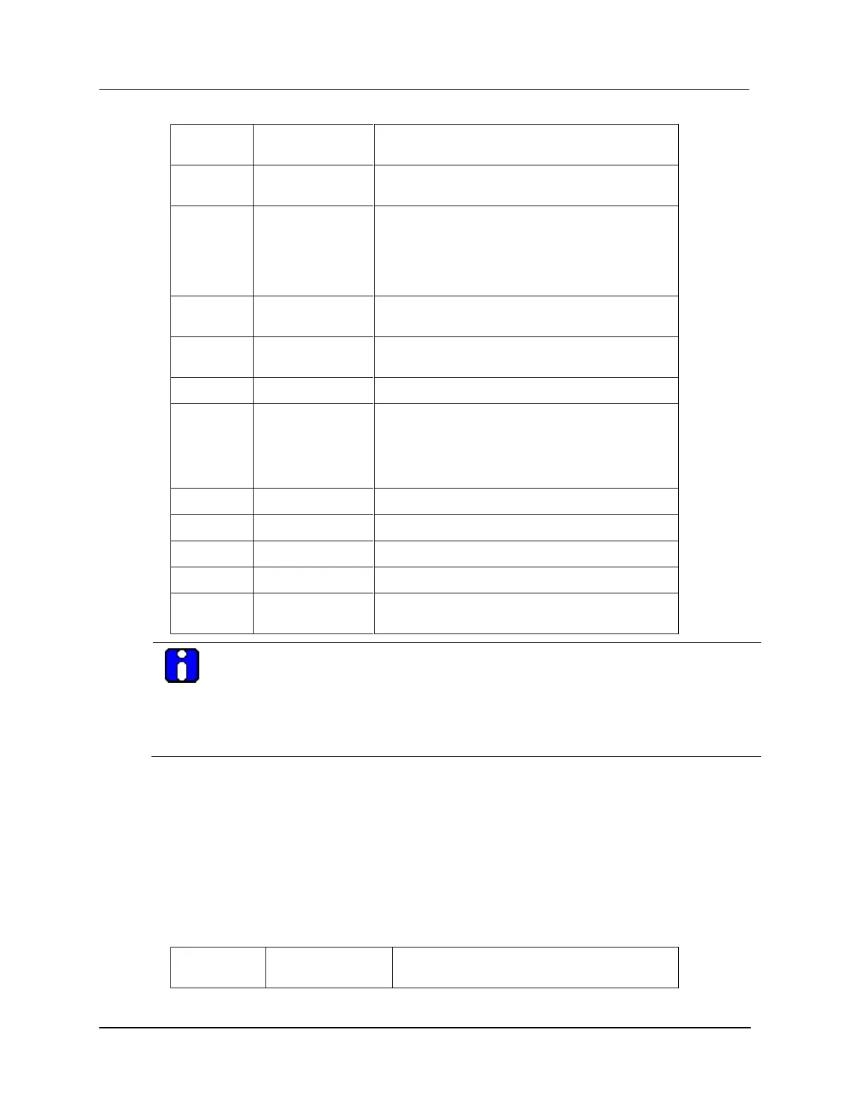
Initialize the (SW resident) LLC Communications
layer.
Start Control processor personality image
download.
Continue with Control processor personality
download.
Monitor Control processor local State Change (i.e.
release Control processor from the reset state).
Control processor Local RAM destructive pattern
test.
Control processor transition to the SW Alive state.
Continue with the Control processor personality
image download (i.e. Control Local RAM portion).
Complete the Control processor personality image
download.
I/O Link RAM destructive pattern test.
Transition I/O Link processor to Idle state.
Backup Local RAM into Global RAM.
HPMM download is completed. This is the HPMM
idle state. (The Idle state display does not blink.)
ATTENTION
The Lxxx message blinks at a 1/2 second rate.
During an HPM personality load for an EHPM node, the message continues to scroll and
repeat. However, the Afnn is replaced with Lfnn. After loading halfway (approximately 2.5
minutes), the display changes to constantly flash Lfnn instead of scrolling the original
detailed information. It continues to flash Lfnn until the EHPM node is fully loaded.
Nonredundant HPM Failure Sequences (After Load)
Comm or I/O Link processor failure (nonredundant HPMM)
A Communications or I/O Link processor failure of a nonredundant HPMM (after transitioning to the
Idle or Run state) results in a blinking Fxxx indication. It enables the detailed display mode using the
Detailed Display switch results in a sequenced Fail/Comm error/Control error display.
The following table lists the display sequence for both the Detailed Display and non-Detailed Display
modes.
Table 72 Communications/I/O Link Processor Failure Display Sequence

 Loading...