EasyManuals Logo
Home>Honeywell>Network Hardware>HPM

Honeywell HPM User Manual

Honeywell HPM
498 pages
To Next Page IconTo Next Page
To Previous Page IconTo Previous Page
Page #97 background imageLoading...
Page #97 background image
2 Equipment Description
2.16 Power Distribution
R688 HPM High-Performance Process Manager Service 97
December 2020 Honeywell
Standard Power System (early production)
Refer to the following figure for the location of the CMOS Battery Backup Assembly mating connector
on the backpanel.
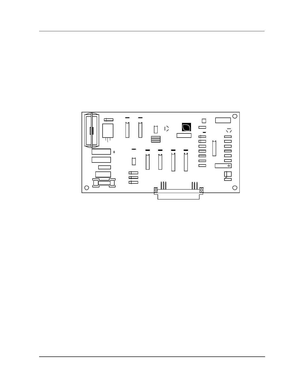
The early production Standard Power System has NiCad batteries located at the upper center of the
Power System chassis backpanel, and the supporting CMOS Battery Backup Assembly is inserted into a
connector at the lower right-hand side of the backpanel. The right Power Supply Module must be
removed to view the assembly. The assembly provides both charging circuitry and a monitoring circuitry
for failure alarm reporting.
See the following figure for an illustration of the CMOS Battery Backup Assembly.
Figure 33 CMOS Battery Backup Assembly (Early Production)
H
J1
U8
C16
U3
F1 - 1 AMP
U10
R16
CR2
CR3
R17
R22
R18
R15
R19
C6
Q1
R10
R9
R8
R5
R6
R7
R13
C2
R11
C7
C10 C11 C13 C12
CR1
VR1
R14
U7
C12
C9
C5
C1
R12
C3
C5
K1
CR4
C6 C8
U6U4
U3
U5
R1
R2
R3
Q2
C1
U2
VR2
R4
ASST. NO. 51303968 - 100
REV
B
CMOS BACKUP ASSY
U1
2510Note: F1 is a 0.5 A time-delay fuse.

Table of Contents

Questions and Answers:

Question and Answer IconNeed help?

Do you have a question about the Honeywell HPM and is the answer not in the manual?

Honeywell HPM Specifications

General IconGeneral
BrandHoneywell
ModelHPM
CategoryNetwork Hardware
LanguageEnglish

Related product manuals