3 UCN Status Displays
3.5 HPM Status Displays
214 HPM High-Performance Process Manager Service R688
Honeywell December 2020
EHPM cannot be loaded, and will also not be shown as “ALIVE” in the UCN Status Display. At least
one FTE cable must be connected for the EHPM to receive an IP address.
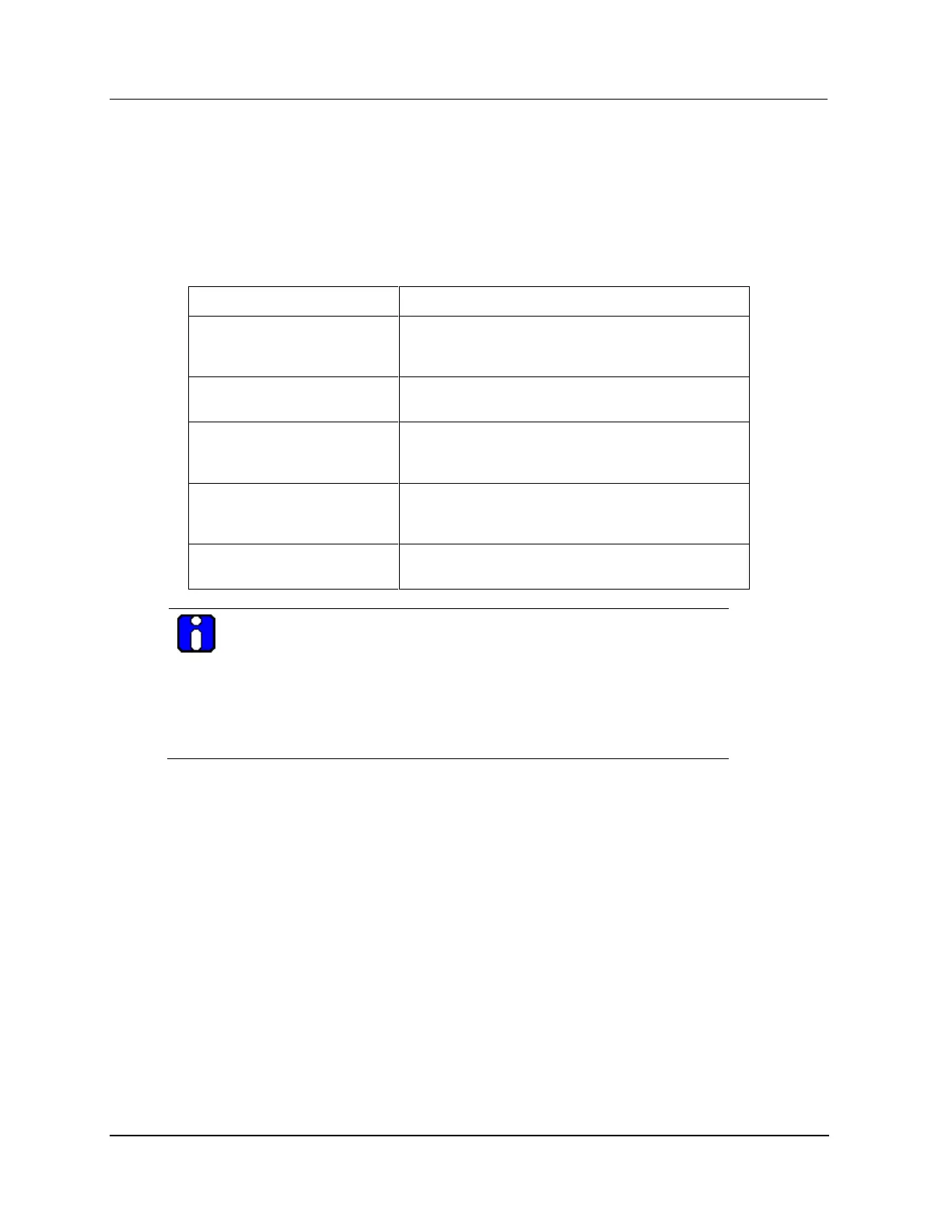
Secondary HPMM status
The possible status of the secondary HPMM is defined in the following table with the color of the text
indicated.
Table 35 HPM Status Display Definitions – Secondary HPMM Status
BACKUP
(Text color – blue)
Processing in the secondary HPMM is in progress
and the secondary database is synchronized with the
primary database.
BKUP_SF
(Text color – blue)
The HPMM is in the Run state, but has a Soft failure.
ALIVE
(Text color – yellow)
Power has been applied to the secondary HPMM, but
no database or personality program was loaded into
the HPMM.
BACKUP
(Text color – yellow)
The secondary HPMM is in the Idle state, or its
database is not synchronized with the primary
HPMM.
BKUP_SF
(Text color – yellow)
The HPMM is in the Idle state, but has a Soft failure.
ATTENTION
The indication of a cable failure is the same for both the traditional coaxial
cable and the FTE. However, with EUCN, the FTE functions through a single
cable fault per node, that is, the FTE functions if there is a fault on Cable A of
one node. Faults on both the Cable A and Cable B of the EUCN are known a
double fault. A double fault causes one or more nodes to be unable to
communicate over the EUCN, resulting in loss-of-view, loss of AM control
and/or loss of peer-to-peer control.
40 IOP status boxes
The IOP information, at the middle grid-like section of the display, defines the status of each IOP. There
are 40 status boxes, representing 40 I/O link addresses. Not all status boxes may be occupied.
IOP status box definitions
The number in the upper left corner of the status box is the I/O Link address assigned to the IOP. The
IOP type is identified in the upper center portion of the status box, such as HLAI or AO. In the center of
the status box is the status of the IOP(s). If a slash (/) appears in the status statement, redundant IOPs, A
and B respectively, are present.
IOP synchronization status
An “S” to the left of IOP A’s status and to the right of IOP B’s status represents the synchronization
status of the redundant IOP pair. The “S” has two backlighting colors, red for SYNC_FAIL and yellow
for SYNC_WARNING. A SYNC_FAIL status indicates the IOP has tried several times to synchronize
the database between the IOPs with no success. A SYNC_WARNING status indicates the IOP is
attempting, or will attempt soon, to synchronize the secondary’s database with the primary’s database.
IOP status states
For redundant Analog Output IOPs, IOP A is the preferred (biased) primary IOP.

 Loading...