7 IOP Calibration Procedures
7.4 LLAI IOP Calibration Procedure
442 HPM High-Performance Process Manager Service R688
Honeywell December 2020
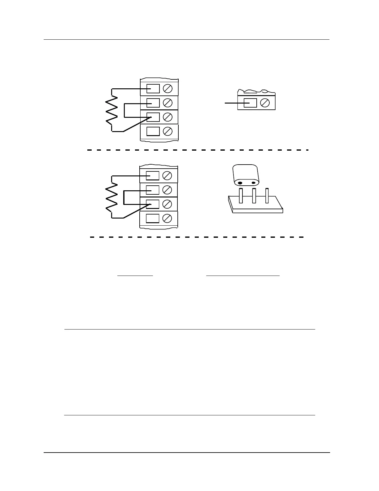
Figure 212 RTD Full Scale Calibration Circuit Cu: 10 Ohm, Pt: 100 Ohm, Ni: 120 Ohm
Be sure there is one wire connected to the "A" terminal and one wire connected to the "B"
terminal. There should be two wires connected to the "C" terminal.
RTD Input Type
Cu: 10 Ohm
Pt: 100 Ohm
Ni: 120 Ohm
100 Ohm
500 Ohm
500 Ohm
Precision Resistor (R cal) Value
Note:
A
B
C
Shield
Model MU/MC-TAIL01 and MU/MC-TAIL02 FTAs
Model MU/MC-TAIL03 FTA
A
B
C
Shield
1 3
Install the jumper between pins 1 and 2.
2
P1
NC
17
TB2
Remove the wire between
TB-1 and TB2-17.
R cal
R cal
Reference
2485
Again, momentarily short the calibration pads at the upper-left corner of the FTA under
test, then check the STATUS indicator (DS1) on the LLAI. The STATUS indicator
remains extinguished for approximately 30 seconds while the IOP card performs its
"full-scale" calibration.
If a thermocouple input is connected to the LLAI subsystem, it is recommended that
you recalibrate the Reference Junction (RJ) input each time the thermocouple is
recalibrated. Only channel 1 requires a zero ohm jumper connected to it.
Connect a zero-ohm jumper to channel 1 as illustrated in Figure 213. Repeat steps 3
and 4.
Connect a 2 kohm resistor jumper to channel 1 as illustrated in Figure 214. Repeat step
6.

 Loading...