2 Equipment Description
2.15 Power Systems
92 HPM High-Performance Process Manager Service R688
Honeywell December 2020
HPM Standard Power System
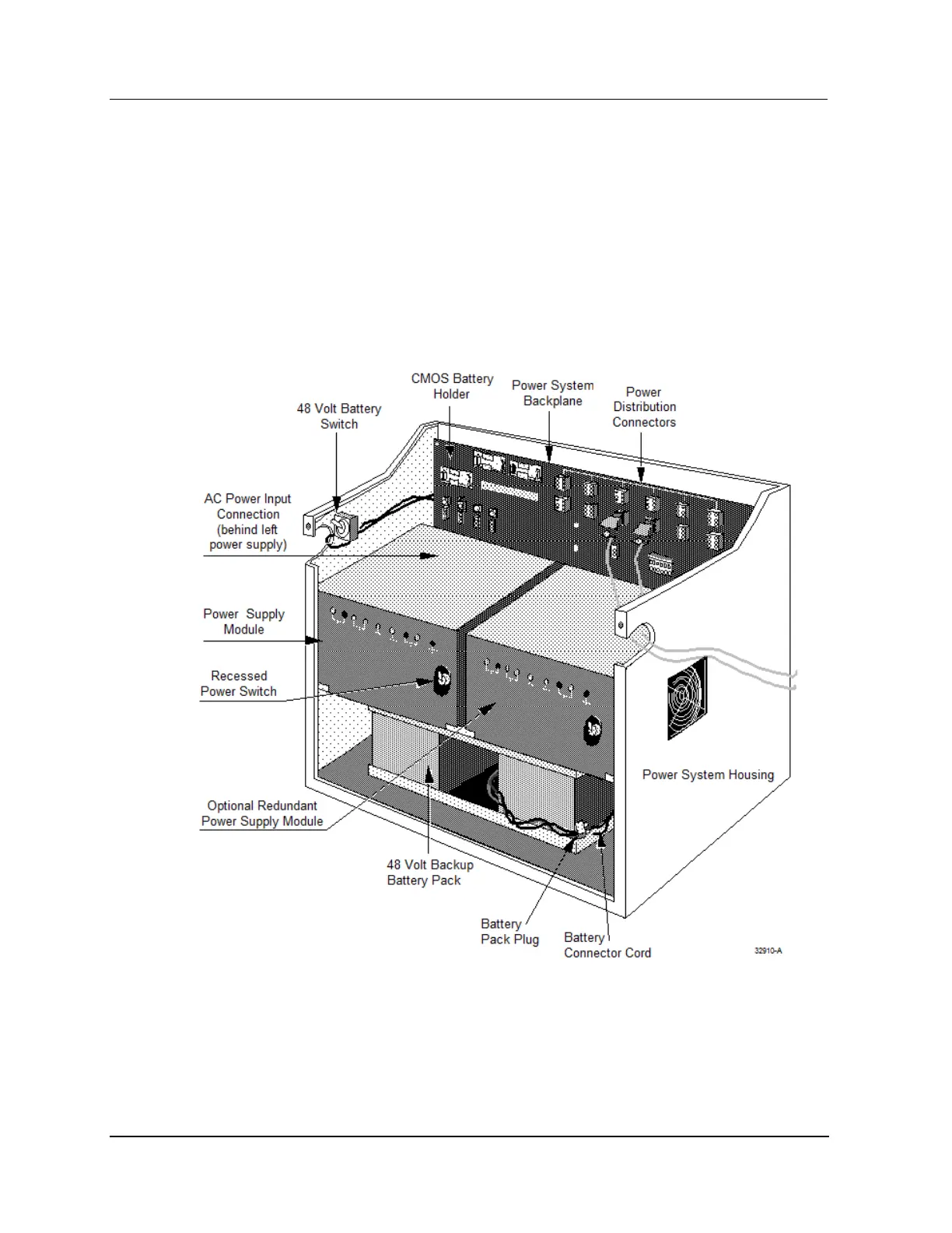
Figure 28 is a illustration of the enhanced HPM Standard Power System configuration that will be
shipped with all new HPM cabinets in the near future. Initial HPM shipments will have an early
production Standard Power System instead. The Power System’s connectors, terminal strips, battery and
fuse holders are an integral part of the Power System backpanel.
There are twelve 24 Vdc power distribution output connectors, four Cabinet Fan Assembly power
connectors with associated fuse holders, and a NiCad battery holder on the backpanel. Sets of terminals
provide alarm signals (for external alarm mechanisms) from each Power Supply Module and the CMOS
Battery Backup. The alarm signals are normally wired in series to a 24 Vdc Digital Input FTA to notify
the system when a Power Supply Module fails.
Figure 28 HPM Standard Power System

 Loading...