4 Fault Isolation
4.9 HPMM Alphanumeric Display
R688 HPM High-Performance Process Manager Service 369
December 2020 Honeywell
Control processor builds memory reference table
I/O Link RAM destructive pattern test
Transition I/O Link processor to the Idle state.
HPMM Redundancy Display Sequences
Each redundant HPMM partner conforms to the Startup sequences as described earlier in this section. In
addition, upon receiving a Swap command, the primary HPMM temporarily displays the SWAP text
while transitioning to a secondary status. However, there is no visible delay while the secondary HPMM
transitions to a primary status. An example of the this sequence is given in the table below.
SWAP sequence (Detailed Display mode)
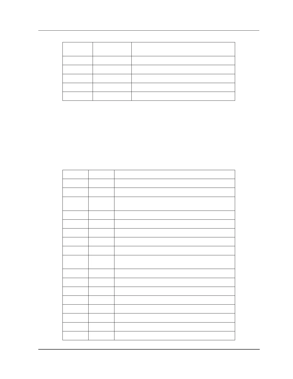
An example of a display sequence during the HPMM swapping process with the Detailed Display mode
enabled is listed in the following figure for HPMM 1 and HPMM 2.
Table 75 Alphanumeric Display for HPMM Swapping Sequence (Detailed Display Mode)
Run state (UCN node 39 = primary/UCN node 40 = Backup )
HPMM swap command received
Communications processor Local RAM destructive pattern
test
Communications processor Local RAM initialization
UCN TBC Private RAM destructive pattern test
UCN TBC Private RAM initialization
Communications processor builds memory reference table.
Transition to the SW Alive state.
Monitor Control processor local state change
(i.e release Control processor from reset state).
Control processor Local RAM destructive pattern test.
Control processor Local RAM initialization.
Control processor builds memory reference table.
I/O Link RAM destructive pattern test.
Transition I/O Link processor to the Idle state.
Secondary HPMM performing database synchronization.

 Loading...