7 IOP Calibration Procedures
7.4 LLAI IOP Calibration Procedure
R688 HPM High-Performance Process Manager Service 443
December 2020 Honeywell
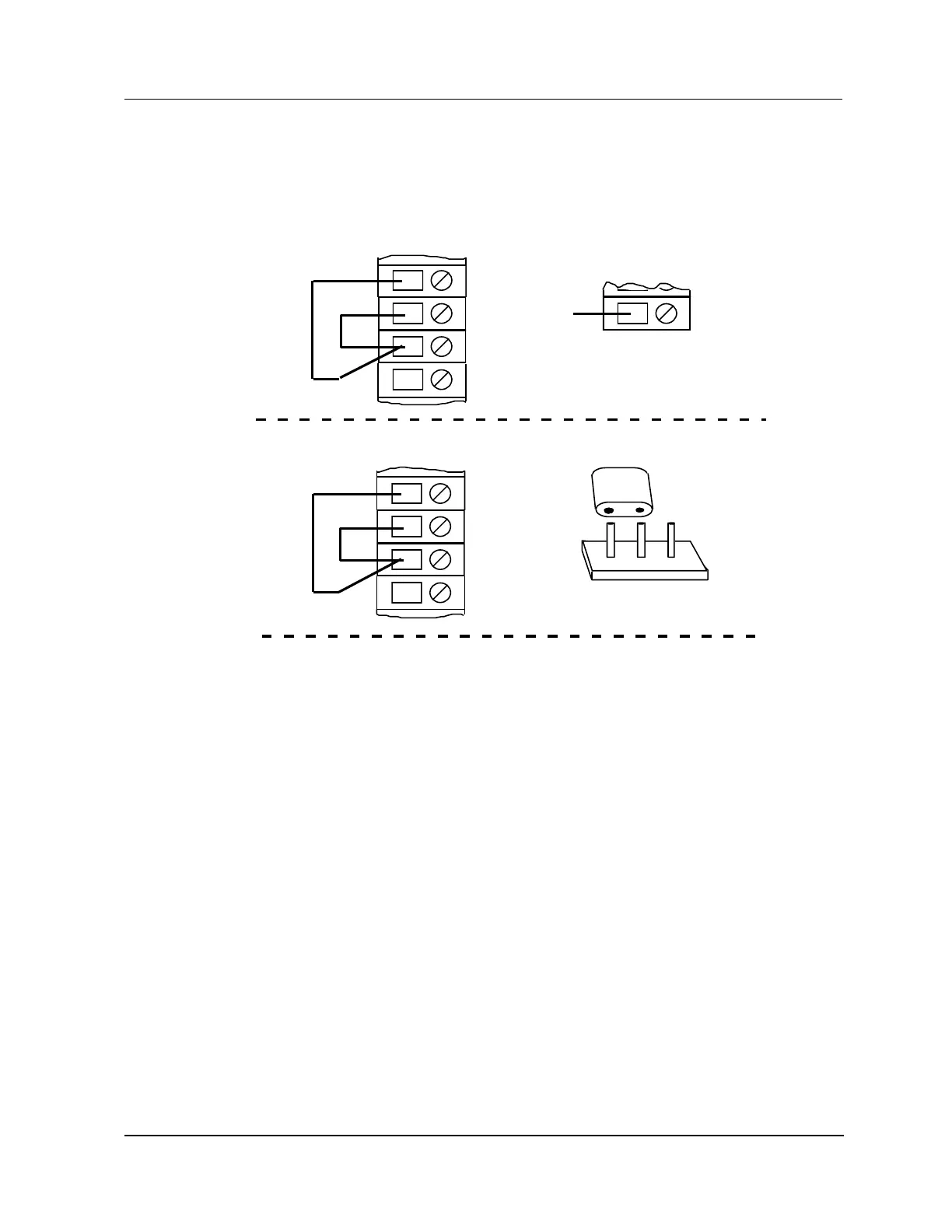
RJ calibration circuit for RJ zero
Figure 213 RJ Calibration Circuit – RJ Zero
Calibrate any time the thermocouple calibration is done. Make the connections to the
terminals for channel 1 only.
Be sure there is one wire connected to the "A" terminal and one wire connected to the "B"
terminal. There should be two wires connected to the "C" terminal.
Note:
A
B
C
Shield
Model MU/MC-TAIL01 and MU/MC-TAIL02 FTAs
Model MU/MC-TAIL03 FTA
A
B
C
Shield
1 3
Install the jumper between pins 1 and 2.
2
P1
NC
17
TB2
Remove the wire between
TB-1 and TB2-17.
Reference
1
2
3
4
TB1
TB1
2486
1
2
3
4

 Loading...