EasyManua.ls Logo

Honeywell HPM User Manual

Honeywell HPM
498 pages
To Next Page IconTo Next Page
To Previous Page IconTo Previous Page
Page #393 background imageLoading...
Page #393 background image
5 UCN Exerciser
5.4 Triangulation Test
R688 HPM High-Performance Process Manager Service 393
December 2020 Honeywell
5.4 Triangulation Test
ATTENTION
This test requires a minimum of one NIM and one server (other UCN nodes). With only two
nodes, the NIM talks point-to-point. Three nodes are required for true triangulation.
Introduction
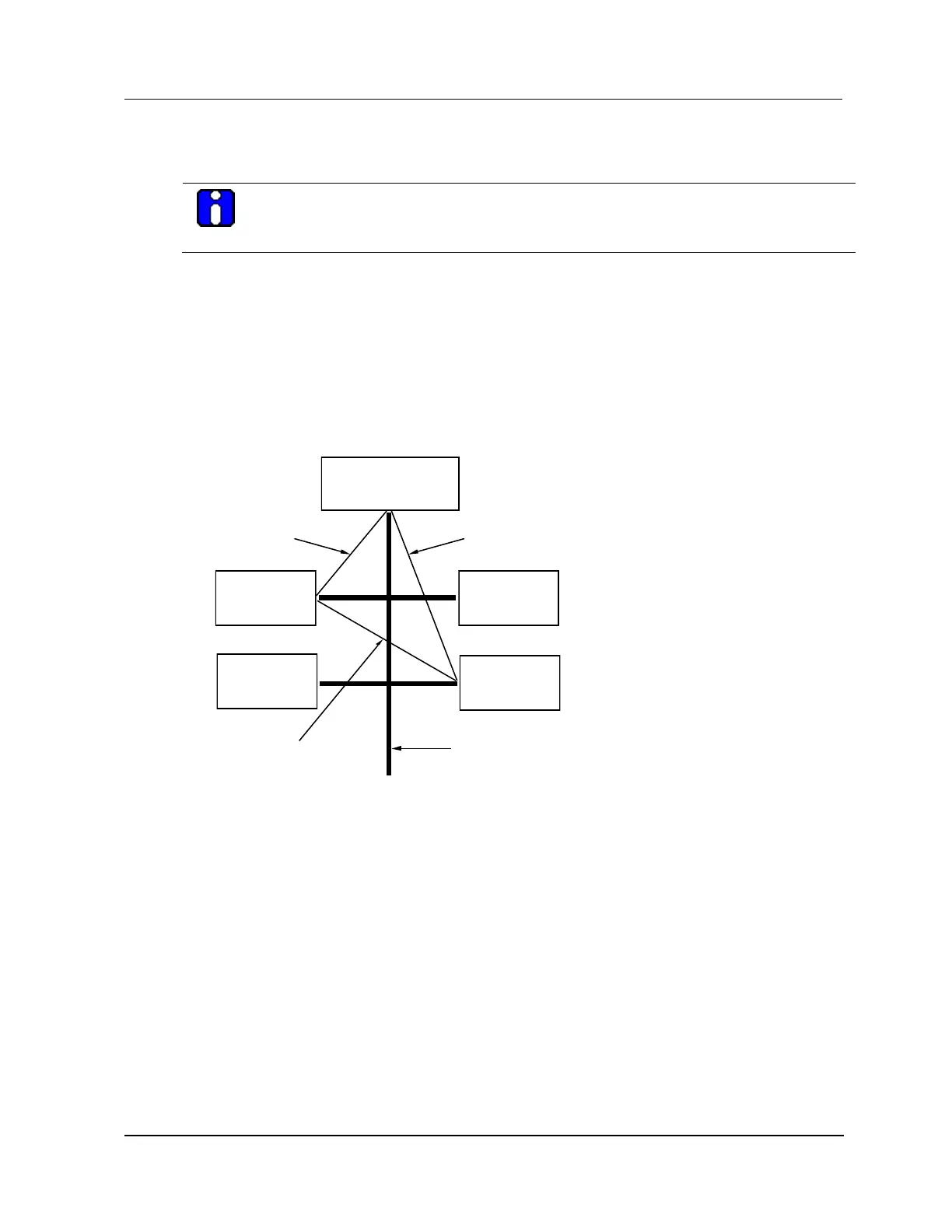
In the triangulation test, as illustrated in the following figure, only nodes that are configured in the test
are capable of token passing participate. For example, HPMs that have not been loaded, cannot pass
tokens and therefore do not participate. For those nodes that do participate, the test Master issues a
message to another node in the test and requests the message to be forwarded to a third node. The third
node in the test then sends a message back to the test Master, which verifies that the path has
successfully completed. While passing the message, the following communication paths are checked:
Master (NIM) to Slave 1, Slave 1 to Slave 2, and Slave 2 to back to the Master.
Figure 192 Triangulation Test
16088
NIM
HPM
HPM
HPM
HPM
(Master)
(Slav e 1)
(Slav e 2)
UCN
(1) Master passes
message to Slave 1
(2) Slav e 1 passes message to Slave 2
(3) Slav e 2 passes
mes sage to MASTER
Timeout policy
Because a message may be lost or an error may occur, the Master has a reasonable timeout policy for
receiving the response back from Slave 2. The timeout policy assumes that each Slave in the test is
serving only one Master. This means that responses arriving late are considered errors. By examining
several paths together, it is usually possible to determine which nodes are experiencing communication
problems.

Table of Contents

Question and Answer IconNeed help?

Do you have a question about the Honeywell HPM and is the answer not in the manual?

Honeywell HPM Specifications

General IconGeneral
BrandHoneywell
ModelHPM
CategoryNetwork Hardware
LanguageEnglish

Summary

2. EQUIPMENT DESCRIPTION

2.3 HPM Subsystem Overview

Provides an overview of the HPM subsystem, including major assemblies and card file types.

2.4 HPMM and IOP Card Files

Discusses differences between HPMM and IOP card files, including models and conversion kits.

2.5 HPMM Card Files

Details HPMM card file configurations, functionality, card types, indicators, and diagnostic displays.

2.6 EHPM Card Files

Describes EHPM card file configurations, functionality, card types, indicators, and diagnostic displays.

2.7 Service failed EHPM cards flashed with Experion-integrated firmware

Provides procedures for servicing failed EHPM cards flashed with Experion-integrated firmware.

2.12 I/O Link Extender (Fiber Optic Link)

Describes I/O Link Extender features, guidelines, front panel indicators, and status indicators.

2.15 Power Systems

Discusses Power System features, types, 48-volt battery backup time, and CMOS backup time.

2.20 24 Vdc Fuse Protection

Details 24 Vdc fuse protection for card files, including fuse removal and insertion.

2.21 5 Vdc Fuse Protection

Covers 5 Vdc fuse protection for High-Performance I/O Link cards and HPMM components.

2.23 I/O Link Interface Cabling

Covers I/O Link interface cabling, including cable length, redundant cables, and shield grounding.

2.26 UCN Cable System

Explains the Universal Control Network (UCN) cable system, including components and cable taps.

2.27 EUCN Cable System

Covers the Enhanced Universal Control Network (EUCN) cable system, including FTE cables and fault diagnosis.

3. UCN Status Displays

4. FAULT ISOLATION

4.2 Failure Types

Defines Hard failures and Soft failures and their impact on HPM and IOP components.

4.6 Redundant Analog Output IOP Failure Diagnosis

Provides a procedure for diagnosing failures in redundant Analog Output IOPs.

5. UCN EXERCISER

6. REMOVAL AND REPLACEMENT

6.2 ESD Guidelines for HPMM and IOP Cards

Provides ESD prevention rules and guidelines for handling HPMM and IOP cards.

6.3 HPMM and IOP Cards

Details removal and replacement procedures for HPMM and IOP cards, including interface modules.

7. IOP CALIBRATION PROCEDURES

7.2 LLAI, HLAI, and AO IOP Calibration

Covers common calibration procedures for LLAI, AO, and HLAI subsystems, including IOP/FTA substitution.

7.4 LLAI IOP Calibration Procedure

Details LLAI IOP calibration, including ranges, slot effects, range selection, and RTD/TC calibration.

7.5 Nonredundant HLAI IOP Calibration Procedure

Provides calibration procedures for nonredundant HLAI FTAs, including connection points and terminals.

7.6 Redundant HLAI IOP Calibration Procedure

Details simultaneous IOP calibration for redundant HLAI IOPs, including connections.

7.7 Nonredundant AO IOP Calibration Procedure

Provides calibration procedures for nonredundant AO IOPs, including isolation and calibration targets.

7.8 Redundant AO IOP Calibration Procedure

Details simultaneous IOP calibration for redundant AO IOPs, requiring specific FTA connections.

8. PERIODIC REDUNDANCY TESTS

8.2 HPMM Redundancy

Discusses HPMM redundancy and how to confirm swap positions using display commands.

8.3 IOP Redundancy

Explains IOP redundancy terminology and provides a test procedure for redundant IOP configurations.

8.4 Redundant 8-Channel Analog Output IOPs

Details redundancy for 8-channel Analog Output IOPs, including hardware identification and test procedures.

8.5 Power Cable Redundancy

Covers redundant power cables for card files and distribution assemblies, including testing procedures.

8.6 Power Supply Module Redundancy

Discusses Power System redundancy and the test procedure for power capability.

9. SPARE PARTS

Related product manuals