2 Equipment Description
2.5 HPMM Card Files
R688 HPM High-Performance Process Manager Service 41
December 2020 Honeywell
HPMM +5 volt power margins
HPMM +5 volt power margining can be accomplished by using the jumper positions under the front
cover of the High-Performance I/O Link card. The possible settings are Normal, High, and Low
margins. Power margining is used by manufacturing test and can also be used for troubleshooting
intermittent hardware problems as a last resort. Power margining is effective as soon as the jumper is
moved.
Honeywell does not recommend the use of power margins on any device that is on-process. Figure 5
High-Performance I/O Link Card (Front Panel) identifies the pinning selections on the
High-Performance I/O Link card with a single jumper.
It is important that the jumper be placed in the Normal position when a nominal voltage level is required
(rather than removing the jumper completely). The jumper in the Normal position is required to
internally set the correct values for error detection (error trip points) at the nominal voltage level.
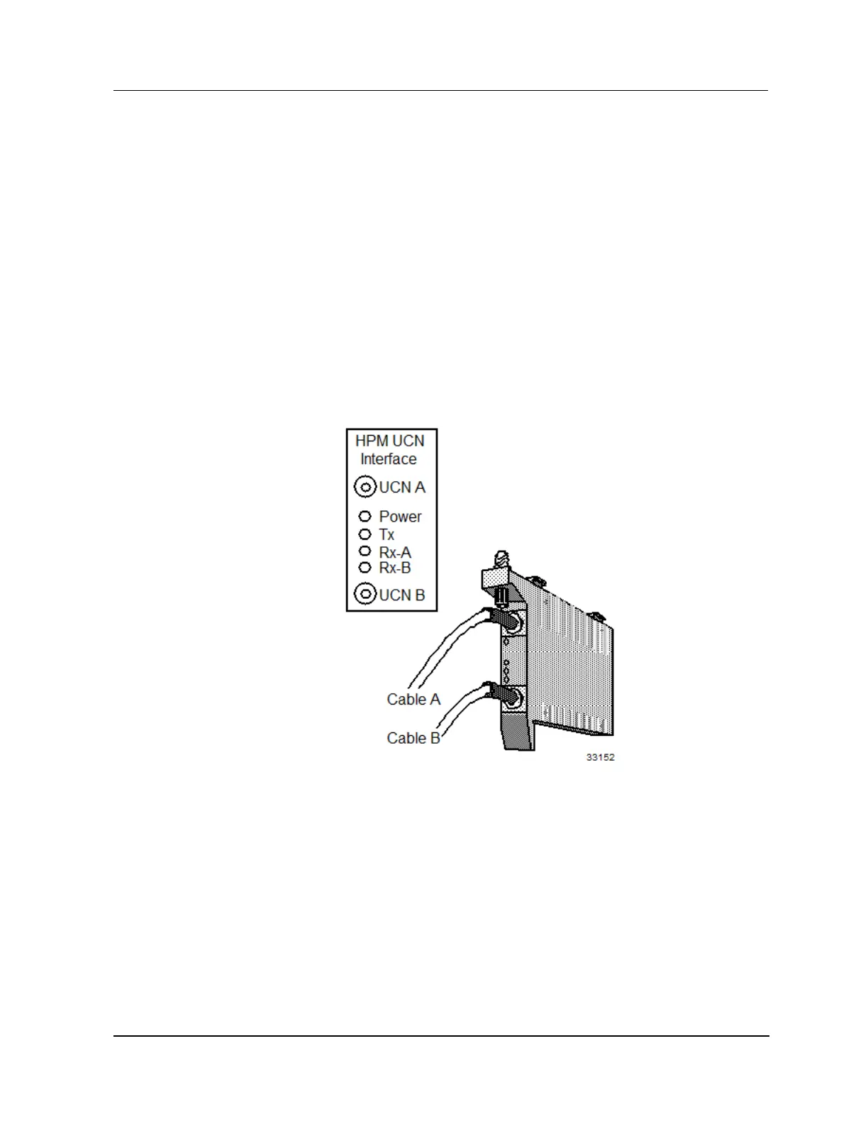
HPM UCN Interface module illustration
The following figure illustrates the front of the HPM UCN Interface module.
Figure 3 HPM UCN Interface Module (Front Panel)

 Loading...