6 Removal and Replacement
6.5 AO Standby Manual Device Operation
410 HPM High-Performance Process Manager Service R688
Honeywell December 2020
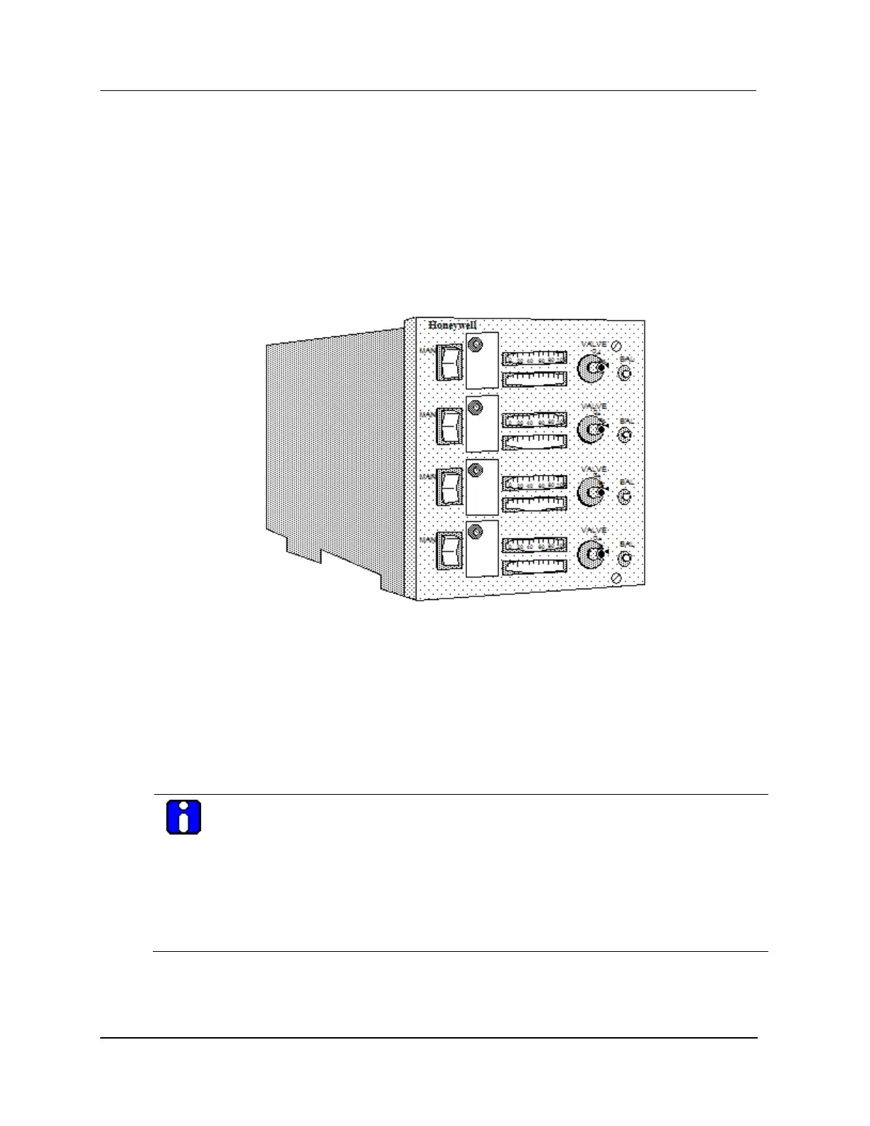
Original Analog Output Standby Manual device
The original model MU-SMAC01/MU-SMAC02 Analog Output Standby Manual (AOSM) device, as
shown in the following figure, monitors the outputs of an Analog Output (AO) IOP by displaying its
output values on meters as a percentage of the range. The following figure illustrates one of the two
Analog Output Standby Manual device assemblies that comprise the Analog Output Standby Manual
device. When you press one of the BAL switches on the Analog Output Standby Manual device, the
corresponding meter indicates the IOP’s output value. Using the VALVE knob, you adjust the Analog
Output Standby Manual device's output to match the output of the IOP. Then, you switch control of the
FTA output to the Standby Manual device by moving the mode switch to the MAN position.
Figure 202 Original Analog Output Standby Manual Device (Two per device)
Control of FTA outputs
To use an Analog Output Standby Manual device to control the FTA outputs to the field while an Analog
Output IOP or the IOP switching module on a redundant Analog Output FTA is being replaced, place all
of the mode switches on the Standby Manual device to the position opposite the MAN position after you
have duplicated the IOP’s outputs.
FTA connection
Connect the Standby Manual device to the STANDBY MANUAL connector on the FTA with its cable.
ATTENTION
If the FTA cable to be connected to the Standby Manual device has a phone-type connector,
use the adapter cable, Honeywell part number 51201561-xxx (The suffix “xxx” represents the
length of the cable in meters), to make the connection.
When a Regulatory Control point indicates its Analog control output is in Standby Manual mode
(STDBYMAN) on an operating display, such as Group or Detail, the output cannot be changed
using that display due to control initialization. To set the point output to match the Analog
Output Standby Manual device setting, the output point must be set using the IOP Slot
Summary display.

 Loading...