CHAPTER 3A ENGINE 260/ 300 / 400 cc ATV SERVICE MANUAL09.0
CHAPTER 3 ENGINE PAGE. 3A- 21
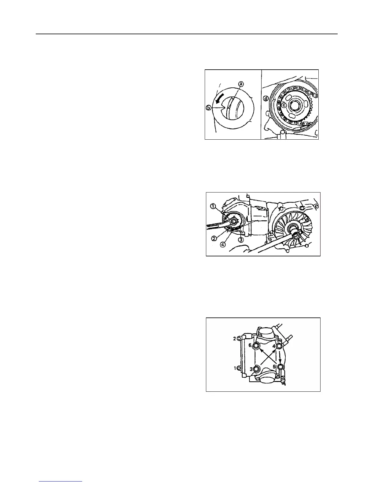
CYLINDER HEAD REMOVAL
1. Align:
"I" mark ○
a
on the rotor
(with stationary pointer ○
b
on the crankcase
cover )
NOTE: If any special mark found, contact the
ATV manufacture via the agent for the parts and
special instruction.
NOTE:
Turn the primary sheave counterclockwise with
a wrench and align the "I" mark ○
c
with the
cylinder head match mark ○
d
when the piston is
at TDC on the compression
2. Loosen:
zBolt c
3. Remove:
zTiming chain tensioner assembly
zTiming chain tensioner gasket
4. Remove:
zBreather plate d
zCam sprocket ③
zTiming chain④
NOTE:
zFasten a safety w ire to the timing chain to
prevent it from falling into the crankcase.
zRemove the bolt c while holding the rotor
mounting bolt with a wrench.
5. Remove:
z Cylinder head
NOTE:
zLoosen the nuts in their proper loosening
sequence.
zStart by loosening each nut 1/2 turn until all
are loose.
 Loading...