Technical Information
11
DGC 6xxx
2 Electrical Components
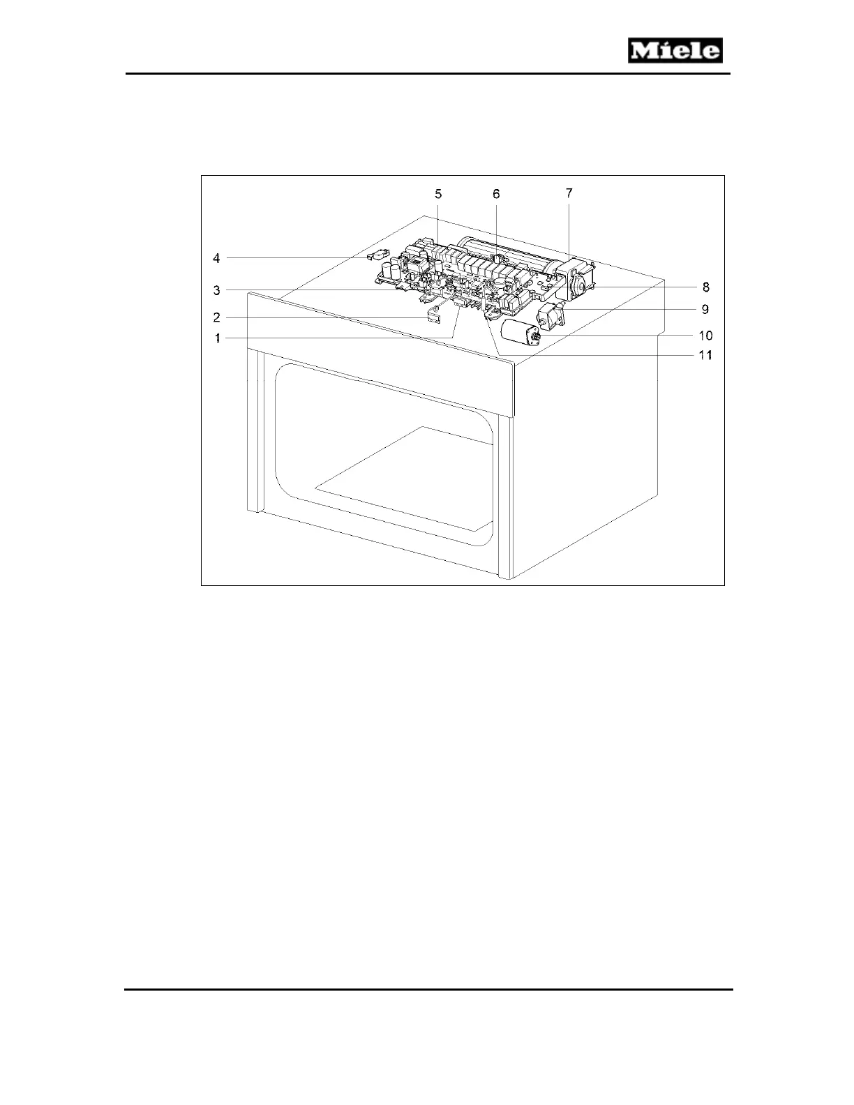
Figure D-2: DGC 6500/6600 Top Components
1
(B3-18) Water tank sensor
2
(B1-2) Overflow switch (actually located next to the drain pump, not by the
electronic as the illustration indicates)
3
(B3-19) Condensate tank sensor
4
(S60) Lift panel position switch
5
(N1-1) Power electronic
6
(1F1) Fan temperature limiter (158°F)
7
(M2-1) Cooling fan
8
(N1-6) Roast probe electronic (with wire connection)
9
(M7) Feed pump
10
(M19) Lift motor
11
(B3-17) Water tank present sensor
 Loading...