Technical Information
87
DGC 6xxx
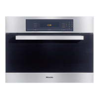
Figure 045-16: Inlet Valve Mounting Bracket
4.10 Air Duct Removal
1. Remove the appliance from its housing unit; see Section 010-4.1.
2. Disconnect the appliance from the power supply.
3. Remove the lid; see Section 010-4.2.
4. Remove the side panels; see Sections 010-4.3 and 010-4.4.
5. Remove the cable duct. See Section 010-4.6.
6. Remove the lighting electronic; see Section 045-4.6.
7. Remove the power electronic; see Section 045-4.8.
8. Disconnect the feed pump, release it from the electronics mounting
bracket and move it to one side (refer to Figure 045-9 as necessary).
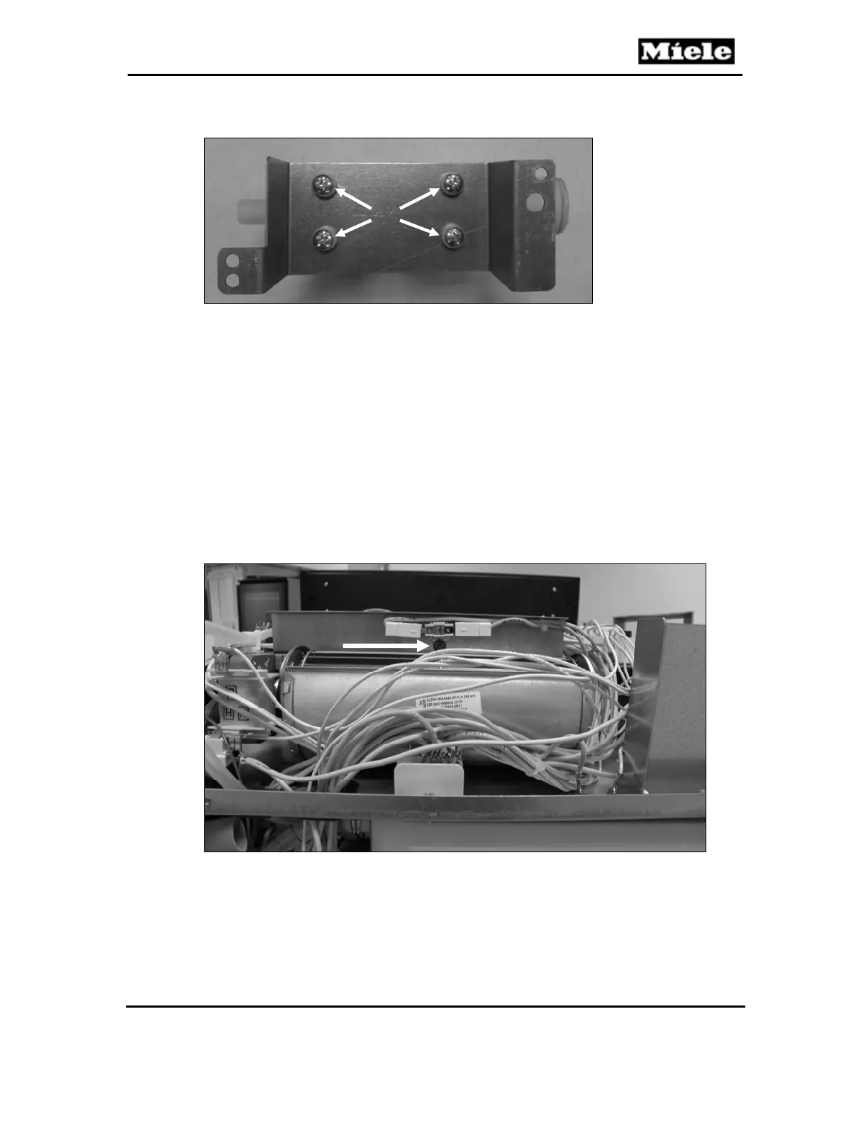
9. Remove the T20 screw securing the cooling-fan temperature limiter to the
back of the electronics mounting bracket. See arrow, Figure 045-17.
Figure 045-17: Cooling-Fan Temperature Limiter
10. Unclip wiring/cables/hoses from their guides on the electronics mounting
bracket as needed.
11. Remove the three T20 screws securing the electronics mounting bracket
to the air duct (Figure 045-18, Item 1). Remove the electronics mounting
bracket from the air duct.
 Loading...