Technical Information
89
DGC 6xxx
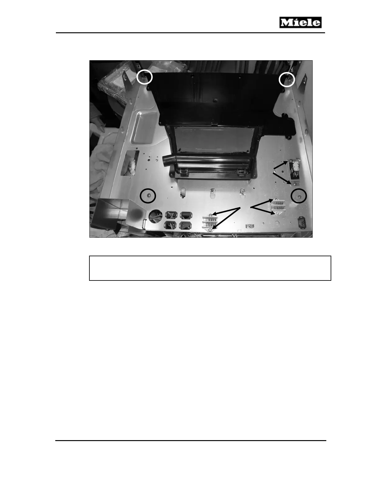
Figure 045-19: Screws Securing Distributors, Position Switch Mounting Bracket and
Air Duct
Note:
There are two additional screws across the front that could not be shown in
Figure 045-19.
4.11 Roast Probe Electronic (N1-6) Removal
1. Remove the appliance from its housing unit; see Section 010-4.1.
2. Disconnect the appliance from the power supply.
3. Remove the lid; see Section 010-4.2.
4. Disconnect the roast probe antenna connection.
5. Disconnect the roast probe electronic (Figure 045-20, Item 1) and release
it from the electronics mounting bracket.
1
2
 Loading...