Technical Information
14
DGC 6xxx
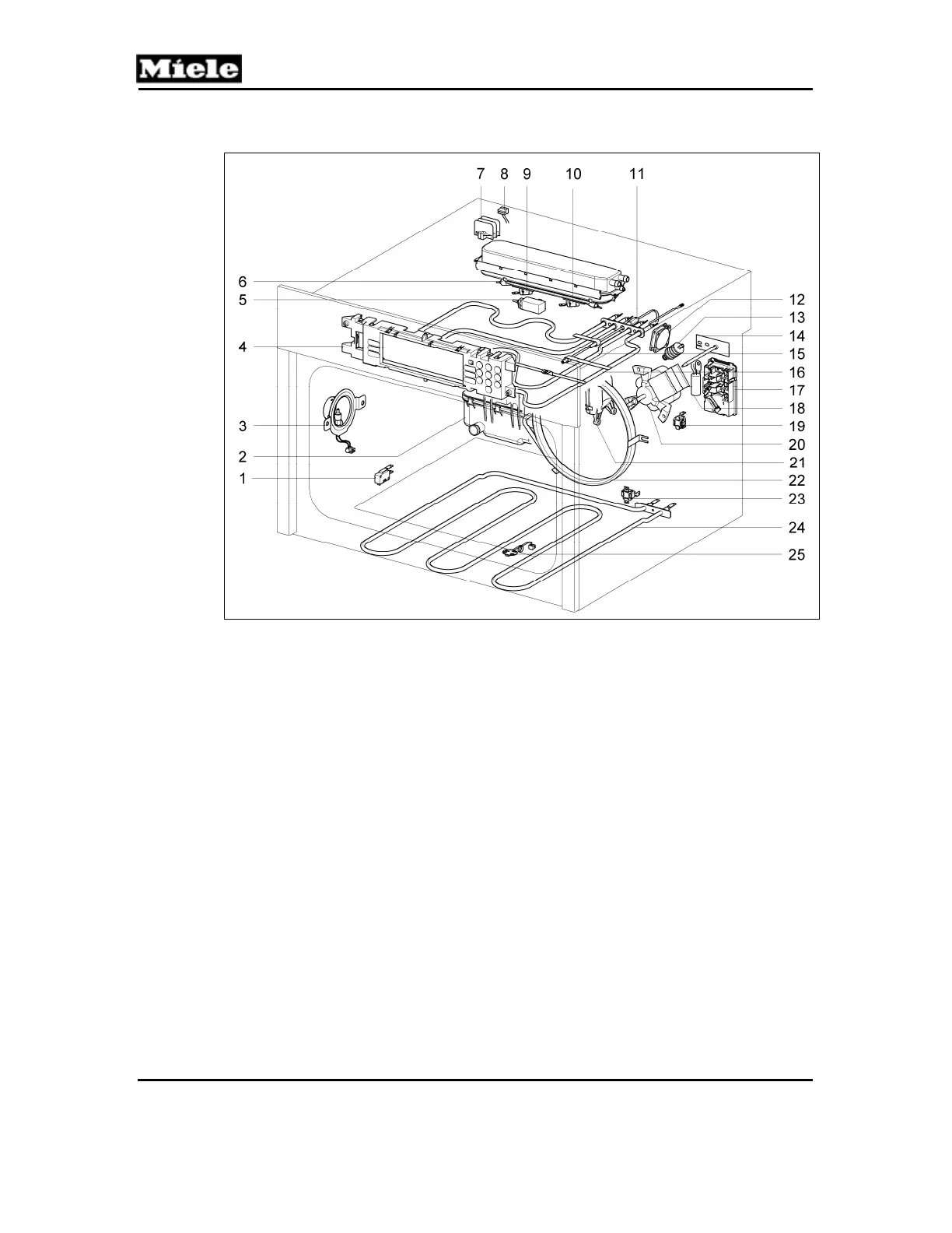
Figure D-5: DGC 670x/680x Cavity and Heating Components
1
(S24) Door contact switch
2
(M8) Drain pump
3
(1H3-2, 2H3-2) Oven cavity lighting
4
(N1-2) EPB/EPZ electronic
5
(M29) Drain valve
6
(1R25, 2R25, 3R25) Steam generator heater elements
7
(1X7) Distributor
8
(X10-1) RemoteVision interface
9
(1F1-5) Steam generator temperature limiter
10
(2F1-5) Steam generator temperature limiter
11
(W17) Roast probe antenna
12
(2M2-1) Heat-flow fan
13
(2R30-10) Heat-flow temperature sensor (Pt 1000)
14
(1R30-10) Oven cavity temperature sensor (Pt 1000)
15
(R15) Broil element
16
(R13) Top heater element
17
(X3-1) Terminal block
18
(Z2) Interference suppression capacitor
19
(3F1) Convection temperature limiter
20
(M2-2) Convection fan
21
(M28) Air flap
22
(R14) Convection heater element
23
(2F1) Bottom heat temperature limiter
24
(R12) Bottom heater element
25
(R30-22) Bottom heat temperature sensor
 Loading...