Technical Information
116
DGC 6xxx
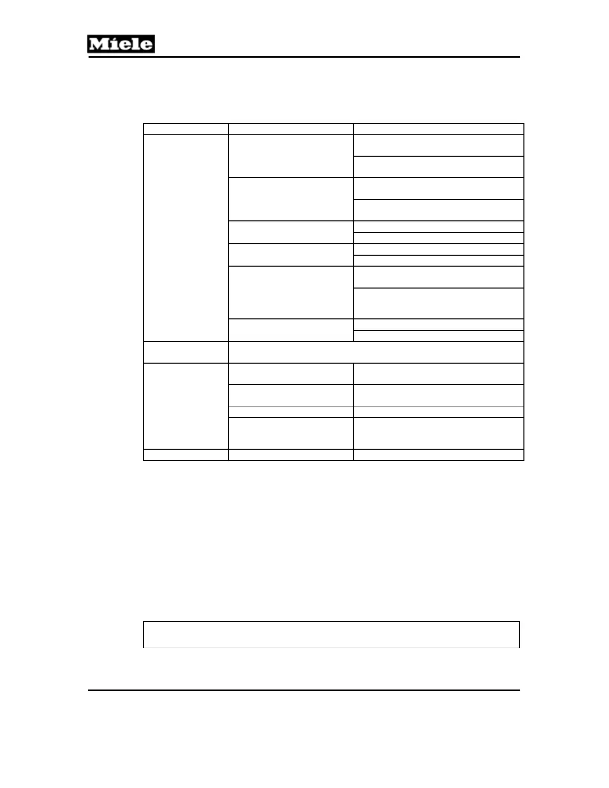
Submenu Function
Description Option
Switch status
B3-18 (water tank sensor).
Insert or remove the water
tank (the tank on the right).
1: Switch closed. Water tank is
installed.
0: Switch open. Water tank is not
installed.
B3-19 (condensate tank
sensor). Install/Remove the
condensate tank.
1: Switch closed. Condensate tank is
installed.
0: Switch open. Condensate tank is not
installed.
B1-2 (drain pump reed
switch)
1: Switch closed. Pump activated.
0: Switch open. Pump not activated.
M28 (air flap)
1: Switch closed.
0: Switch open.
S60 (lift panel position
switch). Open or close the
fascia manually or by
pressing the Lift Panel
button.
1: Lift panel is out and up or all the way
in.
0: Lift panel is straight out.
M29 (pinch valve)
1: Pinch valve closed.
0: Pinch valve open.
Operating hours
(total)
The total machine operating hours figure is displayed.
Operation
Display The display flashes white and the
sensors next to the display flash yellow.
Display backlight Backlight test is displayed and the
display changes from dark to light.
Buzzer/Loudspeaker The buzzer is activated.
(Touch) Sensors A sensor test is carried out where
different values are displayed when the
various touchpad sensors are activated.
Exit
Quit service mode? Yes/No
Table 060-6: Service Mode Functions
1
Always operate the steam generator heater elements with water in the machine.
2
Sensor temperature will be displayed in the units set in the Settings menu (see Section
060-4.1).
Go back, quit:
Go back: Press the Back touchpad.
Quit: Press the touchpad.
4.4 Fascia Panel/Control Electronic Assembly Removal
1. Pull the machine forward by approximately 4 inches or refer to Section
010-4.1.
Warning!
Ensure that the appliance cannot tip.
2. Pull the lift panel all the way out.
 Loading...