Technical Information
41
DGC 6xxx
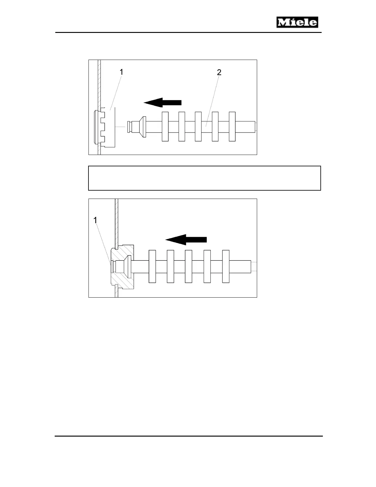
Figure 030-16: Heat-Flow Temperature Sensor Installation
Note:
The temperature sensor must be installed flush with the seal in the cavity
interior; see Figure 030-17, Item 1.
Figure 030-17: Temperature Sensor and Seal
4.10 Roast Probe Socket (X5-8) Removal (Model-Dependent)
1. Remove the appliance from its housing unit; see Section 010-4.1.
2. Disconnect the appliance from the power supply.
3. Remove the lid; see Section 010-4.2.
4. Remove the rear/left side panel; see Section 010-4.4.
5. Open the flap in the cavity and remove the retaining nut, Figure 030-18,
Item 1.
6. Remove the socket.
7. Disconnect the connections from the socket.
 Loading...