Technical Information
35
DGC 6xxx
4.4 Bottom Heater Element Temperature Sensor (R30/22) Removal
1. Remove the door; see Section 020-4.1.
2. Remove the appliance from its housing unit; see Section 010-4.1.
3. Disconnect the appliance from the power supply.
4. Remove the lid; see Section 010-4.2.
5. Remove the side panels; see Sections 010-4.3 and Section 010-4.4.
6. Remove the cable duct; see Section 010-4.6.
7. Remove both hinges; see Section 010-4.7.
8. Unclip the door contact switch from the base plate.
9. Remove residual water from the drain in the cavity using a syringe.
10. Lay the appliance onto its right side.
11. Remove the four T20 screws securing the base plate (see arrows, Figure
030-6) and remove the base plate.
12. Fold open the insulation (release the metal wire ties holding the insulation
in place, if necessary).
13. Remove the two 7mm nuts securing the temperature sensor assembly to
the appliance base, taking care not to lose the washers underneath the
nuts. See arrows, Figure 030-7.
14. Disconnect the temperature sensor from the power electronic.
4.5 Oven Light (1H3-2, 2H3-2) Removal
1. Pull the appliance slightly forward or see Section 010-4.1.
2. Disconnect the appliance from the power supply.
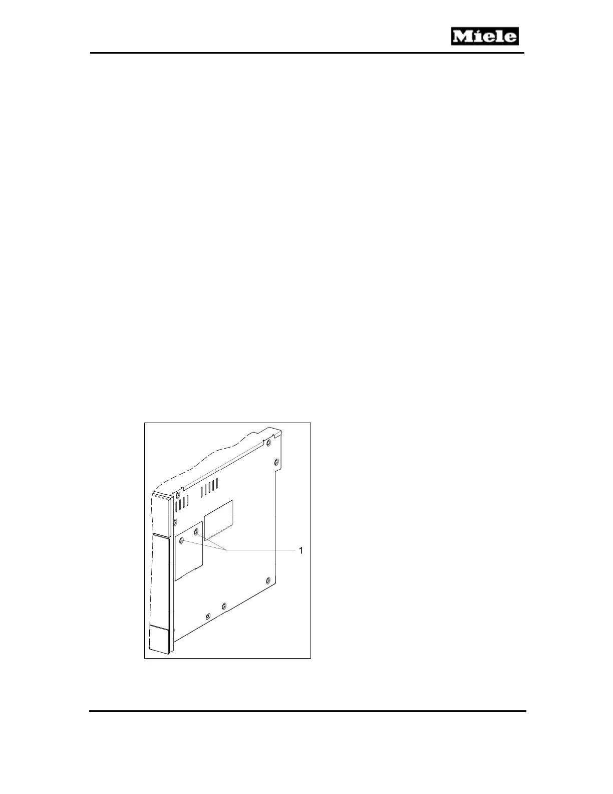
3. Remove the two T20 screws securing the appropriate side service panel;
see Figure 030-9, Item 1.
Figure 030-9: Service Panel Screws
4. Remove the two 7mm nuts securing the appropriate lighting assembly;
 Loading...