Technical Information
55
DGC 6xxx
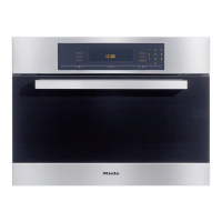
Figure 035-11: Inner Rear Panel Screws
8. Remove the 10mm domed nut securing the fan impeller to the rear of the
oven cavity (left-hand thread!).
9. Remove the fan impeller with serrated washer.
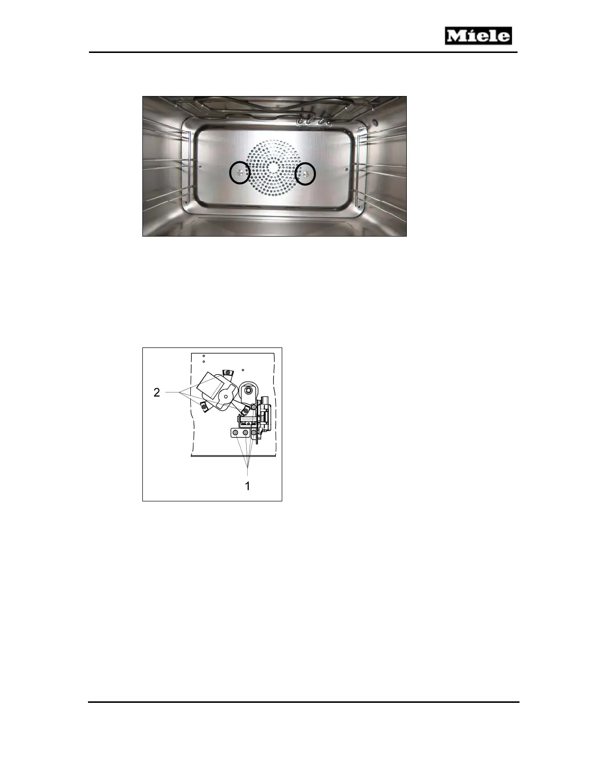
10. Disconnect the convection fan connections at the back of the appliance.
11. Remove the three T20 screws securing the convection fan to the rear wall
of the appliance; see Figure 035-12, Item 2.
12. Remove the convection fan from the rear wall of the appliance.
Figure 035-12: Convection Fan Screws
4.6 Pinch/Drain Valve (M29) Removal
1. Remove the appliance from its housing unit; see Section 010-4.1.
2. Disconnect the appliance from the power supply.
3. Remove the lid; see Section 010-4.2.
4. Remove the rear/left side panel; see Section 010-4.4.
5. Remove the T20 screw securing the right-hand side of the steam
generator mounting bracket (refer to Figure 035-8, Item 1, if necessary).
Release the right-hand side of the bracket.
6. Remove the T20 screw securing the right-hand side of the steam
generator to its mounting bracket (Figure 035-8, Item 2, or Figure 035-9,
Item 1), and swing the steam generator out of the way in order to access
the drain valve screws.
 Loading...