Technical Information
82
DGC 6xxx
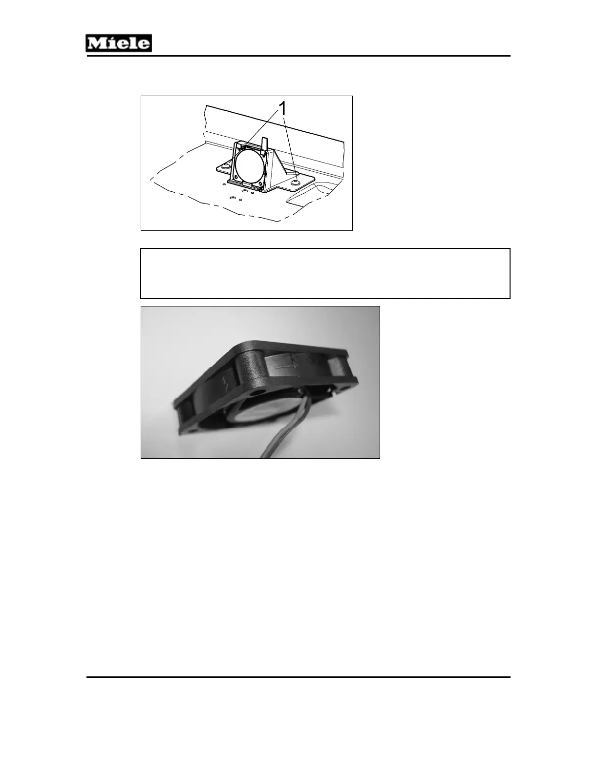
Figure 045-7: Heat-Flow Fan Housing Screws
Note:
When installing the new fan, make sure that its arrows are oriented as
shown in Figure 045-8. The label should be facing out, with its writing
upside down.
Figure 045-8: Heat-Flow Fan Orientation (Top View)
4.3 Feed Pump (M7) Removal
1. Remove the appliance from its housing unit; see Section 010-4.1.
2. Disconnect the appliance from the power supply.
3. Remove the lid; see Section 010-4.2.
4. Disconnect the electrical connections from the feed pump (Figure 045-9,
Item 1).
5. Release the hose connections (Figure 045-9, Item 2).
6. Release the feed pump with its rubber holder (Figure 045-9, Item 3) from
the electronics mounting bracket.
7. Separate the feed pump from the rubber holder.
 Loading...