8 - 2 Operator’s Manual
8 Smart 3D
8.1.2 ROI and VOI
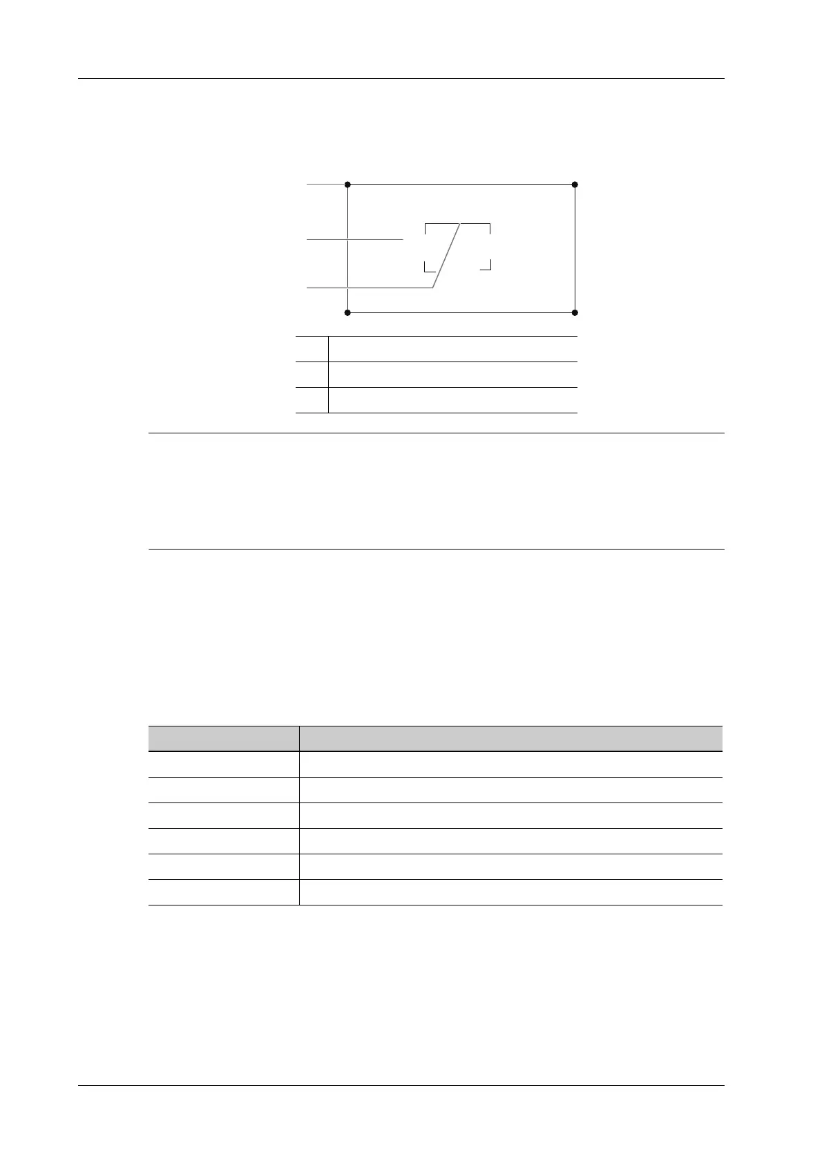
After the system enters 3D imaging, a B image with ROI displays on the screen. A line (shown in
the following figure) that shows the upper edge position of VOI is inside ROI.
• To define a ROI, please remove the useless data as to reduce the volume data and shorten the
time for image storing, processing and reconstruction.
• Set ROI on the 2D image with the largest section area of the fetal face.
• Set ROI a little larger than the fetal head.
ROI size and position
Perform the following procedure:
1. Tap the corner (green dot) of the ROI and drag to change the size.
2. Tap inside the ROI box and drag to change the position.
Curved VOI adjustment
Depending on the view direction, the orientation and the shape (line or dot) of curved VOI vary:
8.1.3 Render Mode
Surface
Set 3D image rendering mode as Surface.
This is helpful for surface imaging, such as fetus face/hand or foot.
1 ROI size adjustment
2 ROI position adjustment
3 Cut plane
View Curved VOI
U/D At the upper part of curved VOI
D/U At the lower part of curved VOI
L/R At the left part of curved VOI
R/L At the right part of curved VOI
F/B Displays as a dot
B/F Displays as a dot
 Loading...


