2 System Overview
Operator’s Manual 2 - 13
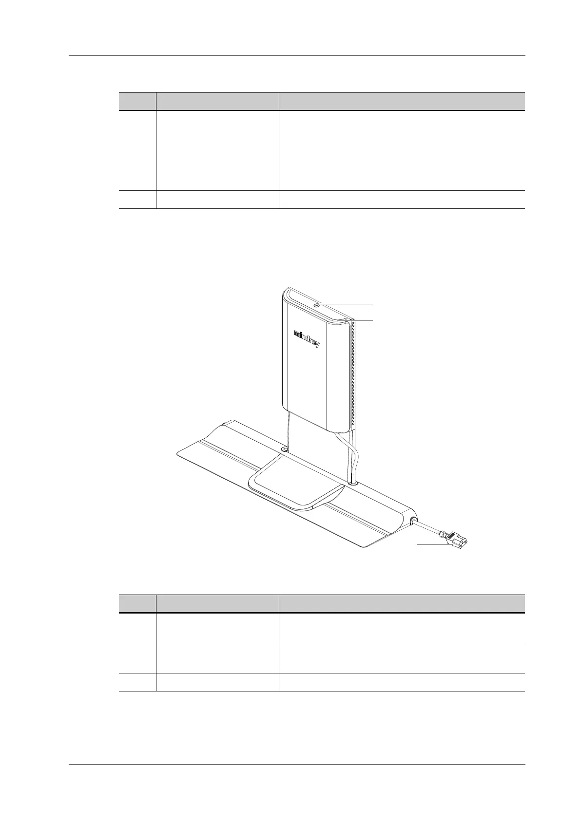
2.10 Air Station
Figure 2-6 Air Station
No. Name Description
1. Serial connector
Connects to the serial port for connecting to ECG of the
system.
NOTE:
Ensure the system is powered off before connecting the
ECG module.
2. ECG lead port Used for ECG signal input.
No. Name Description
1. AC indicator Turns on in white color when connecting the Air Station to
the power supply.
2. Bar indicator Indicates the connection status of wireless charging to the
Air Charge Module.
3. Power cord Connects to power on the Air Station.
1
2
3
 Loading...


