Operating basics
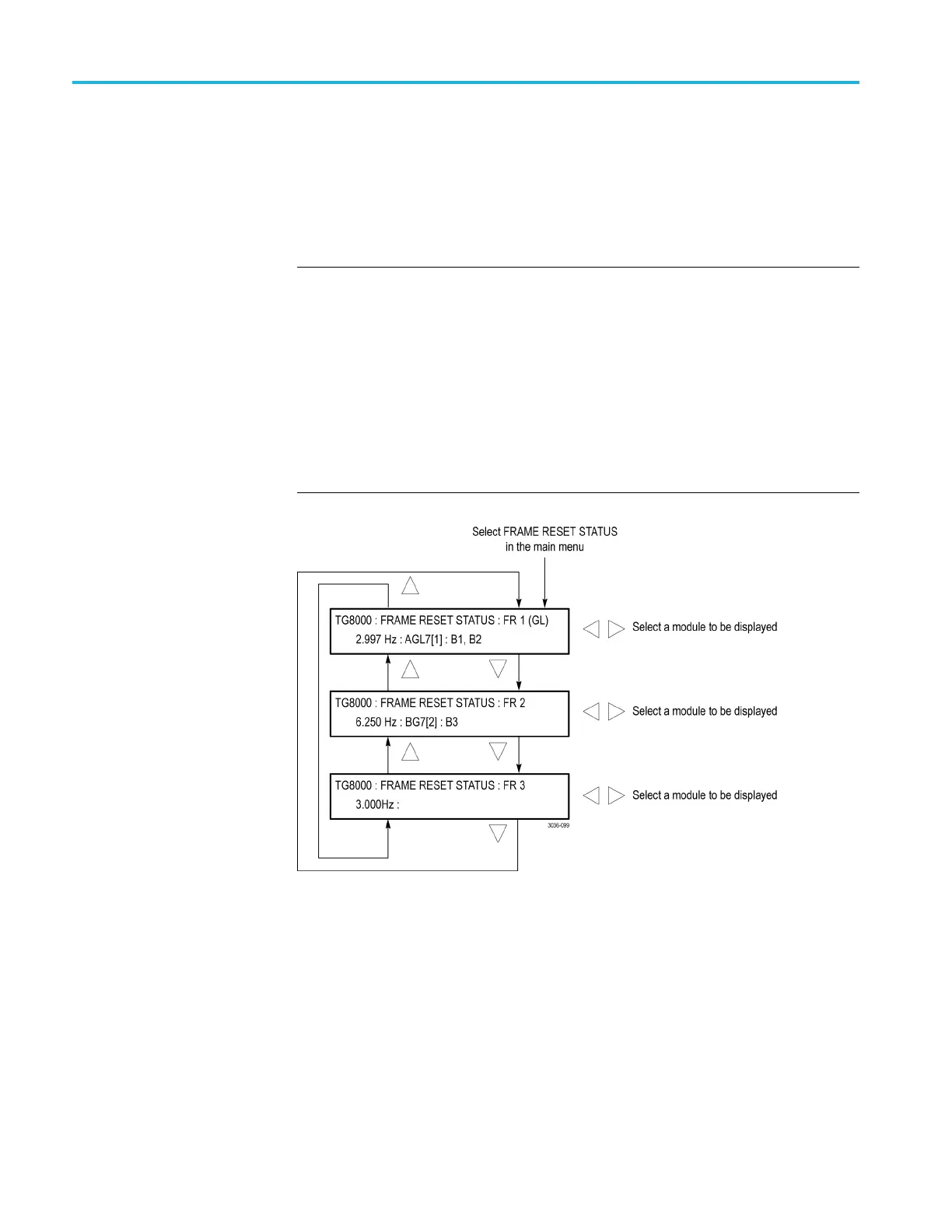
FRAME RESET STAT US
submenu
Use this menu to
display which of the three frame reset signals is used by the
output of the installed modules. Refer to Frame Reset Signals for detailed
information about the frame reset signals. (See page 2-20.)
Use the up (▲) or down (▼) arrow button to scroll through the menu items. The
following figure s hows the FRAME RESET STATUS submenu.
NOTE. The character after the module name represents the output connector of
themodule. Forexample,B1 represents the BLACK 1 connector.
When the TG8000 is genlocked using either an AGL7 or GPS7 module, the text
“(GL)” appears at the end of the line for the frame reset that is being used by the
genlock function. The following figure indicates that the TG8000 is genlocked
using the
AGL7 module and that FRAME RESET 1 is being used by the genlock
function.
As shown
in the following figure for FRAME RESET 3, no module name is
displayed when a frame reset signal is not being used by any of the installed
modules.
Figure 2-20: FRAME RESET STATUS submenu
For each of the frame reset signals, if two or more modules are using the same
frame reset signal , use the left (◄)orright(►) arrow button to select which
modules are displayed.
2–26 TG8000 Multiformat Test Signal Generator User Manual

 Loading...


