Operating basics
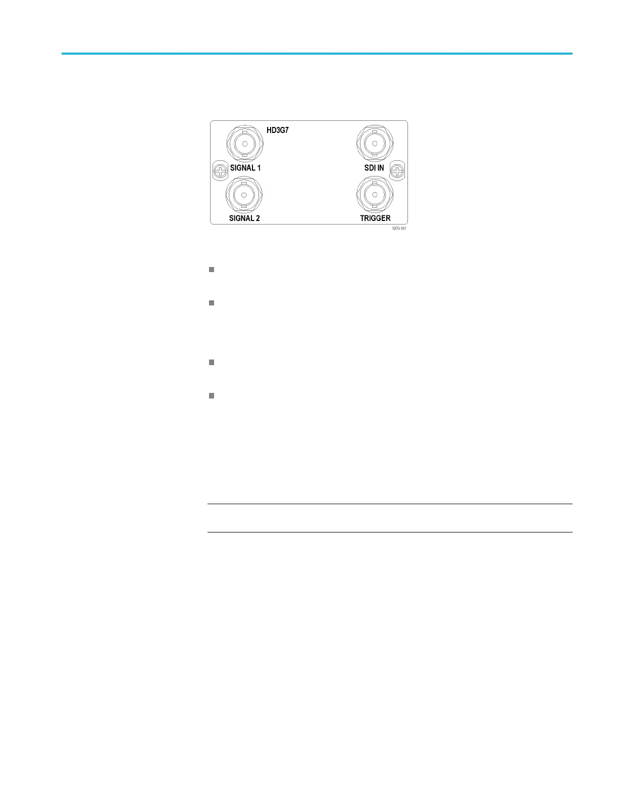
HD3G7 module connectors
The HD3G7 3 Gb/s
SDI Video Generator module provides four BNC connectors
as described below. (See Figure 2-13.)
Figure 2-13: HD3G7 module connectors
SIGNAL 1: Outputs the selected HD-SDI serial digital video test signal or an
upconverted version of the input signal on the SDI IN connector.
SIGNAL 2: The Signal 2 output can be configured to output a test pattern,
where it produces the same output as the Signal 1 output, or to output a Black
signal in the same format as the Signal 1 output. (See page 3-208, HD3G7
module
SECONDARY OUTPUT submenu.)
SDI IN: Input connector for an HD-SDI (4:2:2) video signal that you want to
be upco
nverted.
TRIGGER: Outputs a selected signal. The available choices for output are:
syste
m clock (148.5 MHz), frame/field pulse (once per video frame or field),
or a line pulse (once per video line).
When
an interlaced format is selected, the frame/field pulse selection produces
a frame-rate square wave trigger output which is low during field one and
high during field two. The frame pulse selection produces the once per field
pulse for all other formats.
NOTE. When the SECONDARY OUTPUT selection is set to Test Pattern the
SIGNAL 1 a nd SIGNAL 2 connectors output the same test signal.
TG8000 Multiformat Test Signal Generator User Manual 2–15

 Loading...


