Operating basics
HDLG7 module connectors
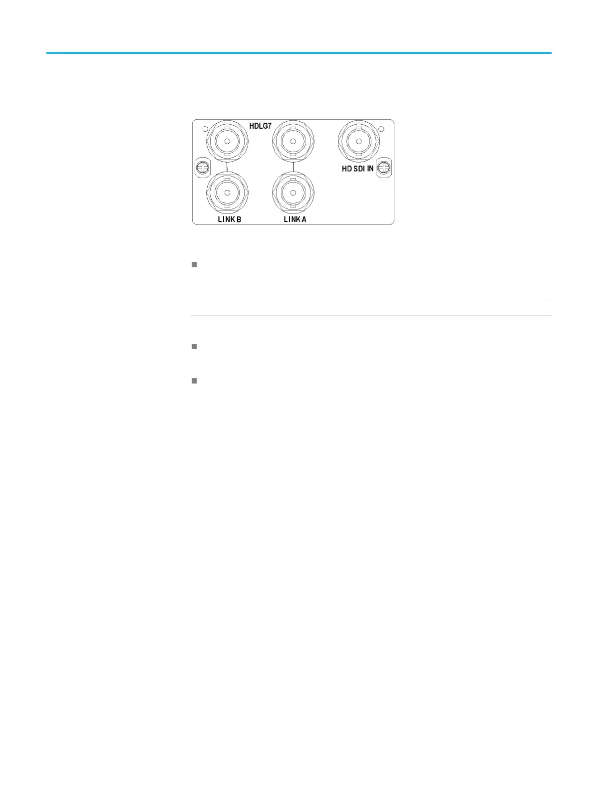
The HDLG7 HD Dua
l Link Video Generator is equipped with five BNC
connectors as described below. (See Figure 2-14.)
Figure 2-14: HDLG7 module connectors
HD SDI IN: Input connector for an HD-SDI (4:2:2) video signal that you
want to be upconverted.
NOTE. Each pair of connectors (LINK A and LINK B) output the same signal.
LINK A: Outputs the selected HD-SDI dual-link video test signal or an
upconverted version of the signal on the HD SDI IN connector.
LINK B: Outputs the selected HD-SDI dual-link video test signal or an
upconverted version of the signal on the HD SDI IN connector.
2–16 TG8000 Multiformat Test Signal Generator User Manual

 Loading...


