Operating basics
AG7 mod ule connectors
The A G7 Audio Ge
nerator module is equipped with six BNC connectors as
described below. (See Figure 2-3.)
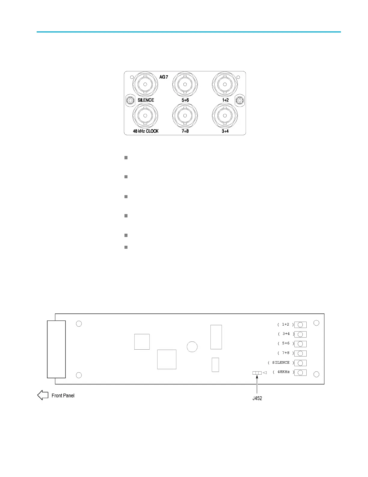
Figure 2-3: AG7 module connectors
1+2: Outputs channels 1 and 2 of the selected AES/EBU serial digital audio
signal.
3+4: Outputs channels 3 and 4 of the selected AES/EBU serial digital audio
signal.
5+6: Outputs channels 5 and 6 of the selected AES/EBU serial digital audio
signal.
7+8: Outputs channels 7 and 8 of the selected AES/EBU serial digital audio
signal.
SILENCE: Outputs a silence signal (DAR signal).
48 kHz CLOCK: Outputs a 48 kHz clock signal. The clock output level
can be set as described below.
Setting the clock output level. Use jumper J452 on the AG7 module to set the
output level of the 48 kHz clock signal. (See Figure 2-4.)
Install the jumper on pins 3+4 of J452 (factory-default position) to set the clock
output level to CMOS compatible. Install the jumper on pins 1+2 of J452 to set
the clock output level to 1V.
Figure 2 -4: Location of J452 on the AG7 module
TG8000 Multiformat Test Signal Generator User Manual 2–7

 Loading...


