


Do you have a question about the Tektronix TG8000 and is the answer not in the manual?
| Brand | Tektronix |
|---|---|
| Model | TG8000 |
| Category | Portable Generator |
| Language | English |
Overview of the TG8000 Multiformat Test Signal Generator and its key features.
Procedure to follow when receiving and inspecting the instrument for damage.
Explains how to add or remove modules from the mainframe as needed.
Details on installing the instrument into an equipment rack, including hardware.
Summary of precautions to prevent injury and product damage.
Additional information for safe product servicing by qualified personnel.
Defines terms used throughout the manual.
Lists EMC directives and standards for European Union compliance.
Lists safety standards and compliance information for the product.
Defines environmental contamination levels and their impact on product use.
Guidelines for equipment recycling and battery disposal according to EU directives.
Lists Tektronix products to which the manual applies.
Describes the manual's composition and sections.
Lists user documents for the TG8000 and related modules.
Explanation of the TG8000 front panel controls and features.
Describes the INT and EXT reference LED indicators and their states.
Overview of TG8000 mainframe and module connectors on the rear panel.
Details the features of the AG7 Audio Generator module, including audio outputs and frequencies.
Procedure to access each function of the AG7 module after installation.
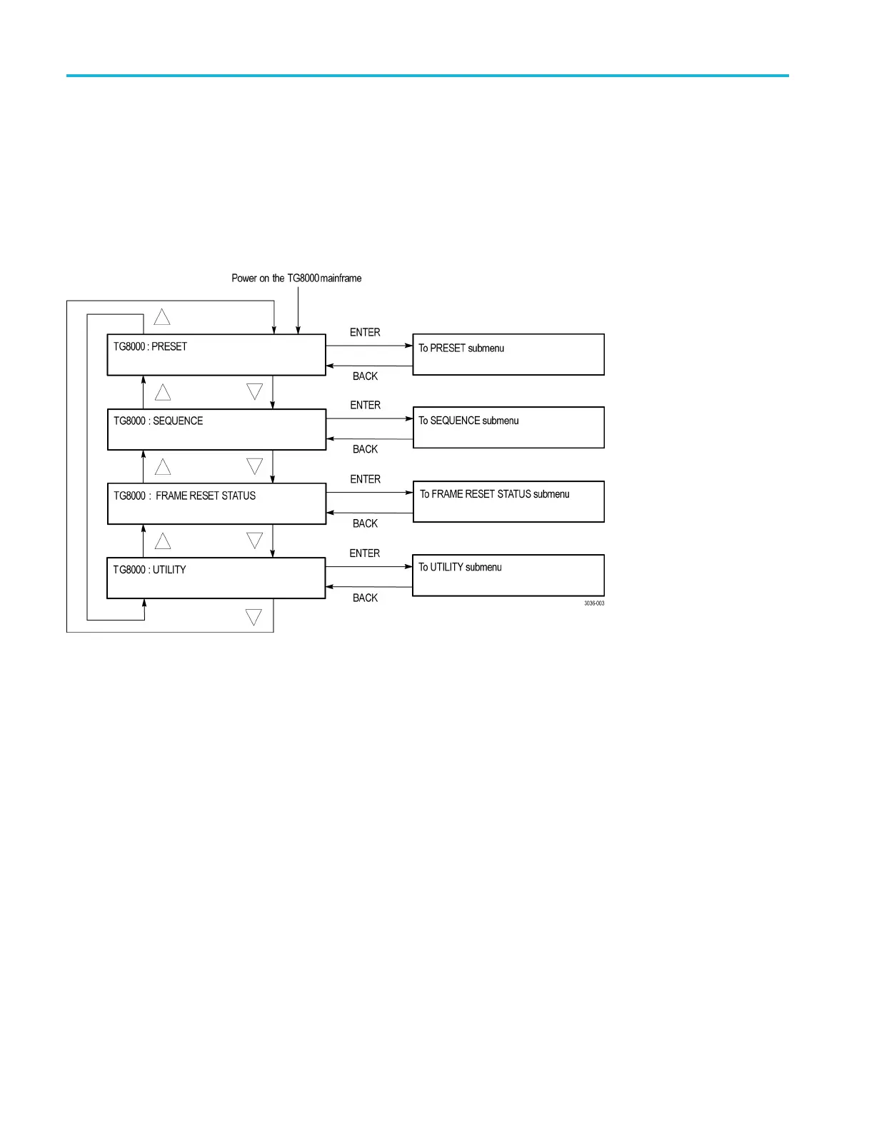
Explains tasks performed using the AG7 module main menu.
Shows factory default settings for the AG7 module, recalled via PRESET menu.
Description of the rear-panel connectors for the AGL7 Analog Genlock module.
Details the features of the AGL7 Analog Genlock module, including genlock signals.
Explains tasks performed using the AGL7 module main menu to select genlock source and outputs.
Sets signal format and timing offset for selected output connectors like BLACK 1, 2, or 3.
Description of the rear-panel connectors for the ATG7 Analog Test Generator module.
Basic procedure to check the functionality of the ATG7 module.
Details features of the ATG7 Analog Test Generator, including output connectors and formats.
Steps to select signal format and test signal for output from SIGNAL connector.
Description of the rear-panel connectors for the AVG7 Analog Video Generator module.
Basic procedure to check the functionality of the AVG7 module.
Details features of the AVG7 Analog Video Generator, including supported formats and outputs.
Procedure to access each function of the AVG7 module after installation.
Description of the rear-panel connectors for the AWVG7 Analog Wideband Video Generator module.
Basic procedure to check the functionality of the AWVG7 module.
Details features of the AWVG7 Analog Wideband Video Generator, including supported formats and outputs.
Steps to select signal format for the AWVG7 module output.
Description of the rear-panel connectors for the BG7 Black Generator module.
Basic procedure to check the functionality of the BG7 module.
Details features of the BG7 Black Generator, including outputs and capabilities.
Explains tasks performed using the BG7 module main menu to select outputs and format.
Description of the rear-panel connectors for the DVG7 Digital Video Generator module.
Basic procedure to check the functionality of the DVG7 module.
Details features of the DVG7 Digital Video Generator, including outputs and audio capabilities.
Steps to select signal format for the DVG7 module output.
Description of the rear-panel connectors for the GPS7 GPS Synchronization and Timecode module.
Basic procedure to check the functionality of the GPS7 module.
Details features of the GPS7 module, including GPS receiver, timecode, and outputs.
Essential steps and information before putting the GPS7 module into service.
Description of the rear-panel connectors for the HD3G7 HD 3 Gb/s SDI Video Generator module.
Basic procedure to check the functionality of the HD3G7 module.
Details features of the HD3G7 module, including operating modes and outputs.
Procedures for selecting output signals based on operation mode (generator or converter).
Description of the rear-panel connectors for the HDLG7 HD Dual Link Video Generator module.
Basic procedure to check the functionality of the HDLG7 module.
Details features of the HDLG7 module, including operating modes and outputs.
Procedures for selecting output signals based on operation mode (converter or generator).
Description of the rear-panel connectors for the HDVG7 HDTV Digital Video Generator module.
Basic procedure to check the functionality of the HDVG7 module.
Details features of the HDVG7 module, including outputs, supported formats, and audio capabilities.
Steps to select signal format and HD trilevel sync rate for the HDVG7 module.
Description of the rear-panel connectors for the SDI7 Dual Channel SD/HD/3G SDI Video Generator module.
Basic procedure to check the functionality of the SDI7 module.
Details features of the SDI7 module, including output capabilities and formats.
Steps to enter option keys for software upgrades like Option 3G and DBT.
Steps to determine if the instrument firmware requires an upgrade by checking versions.
Procedure for upgrading firmware using a USB drive connected to the PC.
Procedure for upgrading firmware via Ethernet network connection to the instrument.
Explains the process of copying files to/from a USB drive for backup/restore.
Guide to inspecting the instrument's outside for damage, wear, and missing parts.
Steps for cleaning the exterior of the instrument, including the monitor screen.
Description of the rear-panel connectors for the AG7 Audio Generator module.
Basic procedure to check the functionality of the AG7 module.
Explains tasks performed using the AG7 module main menu.
Adjusts timing offset of audio signal outputs relative to the internal reference signal.
Description of the rear-panel connectors for the AGL7 Analog Genlock module.
Basic procedure to check the functionality of the AGL7 module.
Details the features of the AGL7 Analog Genlock module, including genlock signals.
Information regarding FPGA updates for AGL7 module during TG8000 firmware upgrades.
Description of the rear-panel connectors for the ATG7 Analog Test Generator module.
Basic procedure to check the functionality of the ATG7 module.
Details features of the ATG7 Analog Test Generator, including output connectors and formats.
Steps to select the signal format for the ATG7 module output.
Description of the rear-panel connectors for the AVG7 Analog Video Generator module.
Basic procedure to check the functionality of the AVG7 module.
Details features of the AVG7 Analog Video Generator, including supported formats and outputs.
Explains tasks performed using the AVG7 module main menu.
Description of the rear-panel connectors for the AWVG7 Analog Wideband Video Generator module.
Basic procedure to check the functionality of the AWVG7 module.
Details features of the AWVG7 Analog Wideband Video Generator, including supported formats and outputs.
Explains tasks performed using the AWVG7 module main menu.
Description of the rear-panel connectors for the HD3G7 HD 3 Gb/s SDI Video Generator module.
Basic procedure to check the functionality of the HD3G7 module.
Details features of the HD3G7 module, including operating modes and outputs.
Procedures for selecting output signals based on operation mode (generator or converter).
Description of the rear-panel connectors for the HDLG7 HD Dual Link Video Generator module.
Basic procedure to check the functionality of the HDLG7 module.
Details features of the HDLG7 module, including operating modes and outputs.
Procedures for selecting output signals based on operation mode (converter or generator).
Description of the rear-panel connectors for the HDVG7 HDTV Digital Video Generator module.
Basic procedure to check the functionality of the HDVG7 module.
Details features of the HDVG7 module, including outputs, supported formats, and audio capabilities.
Steps to select signal format and HD trilevel sync rate for the HDVG7 module.
Description of the rear-panel connectors for the SDI7 Dual Channel SD/HD/3G SDI Video Generator module.
Basic procedure to check the functionality of the SDI7 module.
Details features of the SDI7 module, including output capabilities and formats.
Steps to enter option keys for software upgrades like Option 3G and DBT.
Steps to select a zone plate signal for output from the SWEEP button menu.
How to create and save modified zone plate signals by changing parameters.
Selects SD, HD, or 3G-SDI serial link multiplexing (Level A/B).
Selects sample structures and depth for non-fast-progressive formats.
Sets ancillary timecode (ATC) parameters for the selected output.
Modifies video output signal, enabling/disabling components, edge filtering, EDH, and AV Timing mode.
Procedure for upgrading firmware using a USB drive connected to the PC.
Procedure for upgrading firmware via Ethernet network connection to the instrument.
Explains the process of copying files to/from a USB drive for backup/restore.
Instructions for transferring user files to/from the generator using an FTP client.
Guide to inspecting the instrument's outside for damage, wear, and missing parts.
Steps for cleaning the exterior of the instrument, including the monitor screen.
Description of the rear-panel connectors for the AG7 Audio Generator module.
Basic procedure to check the functionality of the AG7 module.
Explains tasks performed using the AG7 module main menu.
Shows factory default settings for the AG7 module, recalled via PRESET menu.
Description of the rear-panel connectors for the AGL7 Analog Genlock module.
Basic procedure to check the functionality of the AGL7 module.
Details the features of the AGL7 Analog Genlock module, including genlock signals.
Selects genlock source, timing offset, and actions for loss of lock.
Description of the rear-panel connectors for the ATG7 Analog Test Generator module.
Basic procedure to check the functionality of the ATG7 module.
Details features of the ATG7 Analog Test Generator, including output connectors and formats.
Explains tasks performed using the ATG7 module main menu.
Description of the rear-panel connectors for the AVG7 Analog Video Generator module.
Basic procedure to check the functionality of the AVG7 module.
Details features of the AVG7 Analog Video Generator, including supported formats and outputs.
Explains tasks performed using the AVG7 module main menu.
Description of the rear-panel connectors for the AWVG7 Analog Wideband Video Generator module.
Basic procedure to check the functionality of the AWVG7 module.
Details features of the AWVG7 Analog Wideband Video Generator, including supported formats and outputs.
Explains tasks performed using the AWVG7 module main menu.
Description of the rear-panel connectors for the HD3G7 HD 3 Gb/s SDI Video Generator module.
Basic procedure to check the functionality of the HD3G7 module.
Details features of the HD3G7 module, including operating modes and outputs.
Procedures for selecting output signals based on operation mode (generator or converter).
Description of the rear-panel connectors for the HDLG7 HD Dual Link Video Generator module.
Basic procedure to check the functionality of the HDLG7 module.
Details features of the HDLG7 module, including operating modes and outputs.
Procedures for selecting output signals based on operation mode (converter or generator).
Description of the rear-panel connectors for the HDVG7 HDTV Digital Video Generator module.
Basic procedure to check the functionality of the HDVG7 module.
Details features of the HDVG7 module, including outputs, supported formats, and audio capabilities.
Steps to select signal format and HD trilevel sync rate for the HDVG7 module.
Description of the rear-panel connectors for the SDI7 Dual Channel SD/HD/3G SDI Video Generator module.
Basic procedure to check the functionality of the SDI7 module.
Details features of the SDI7 module, including output capabilities and formats.
Steps to enter option keys for software upgrades like Option 3G and DBT.
Steps to select a zone plate signal for output from the SWEEP button menu.
How to create and save modified zone plate signals by changing parameters.
Selects SD, HD, or 3G-SDI serial link multiplexing (Level A/B).
Selects sample structures and depth for non-fast-progressive formats.
Sets ancillary timecode (ATC) parameters for the selected output.
Modifies video output signal, enabling/disabling components, edge filtering, EDH, and AV Timing mode.


