Operating basics
ATG7 module connectors
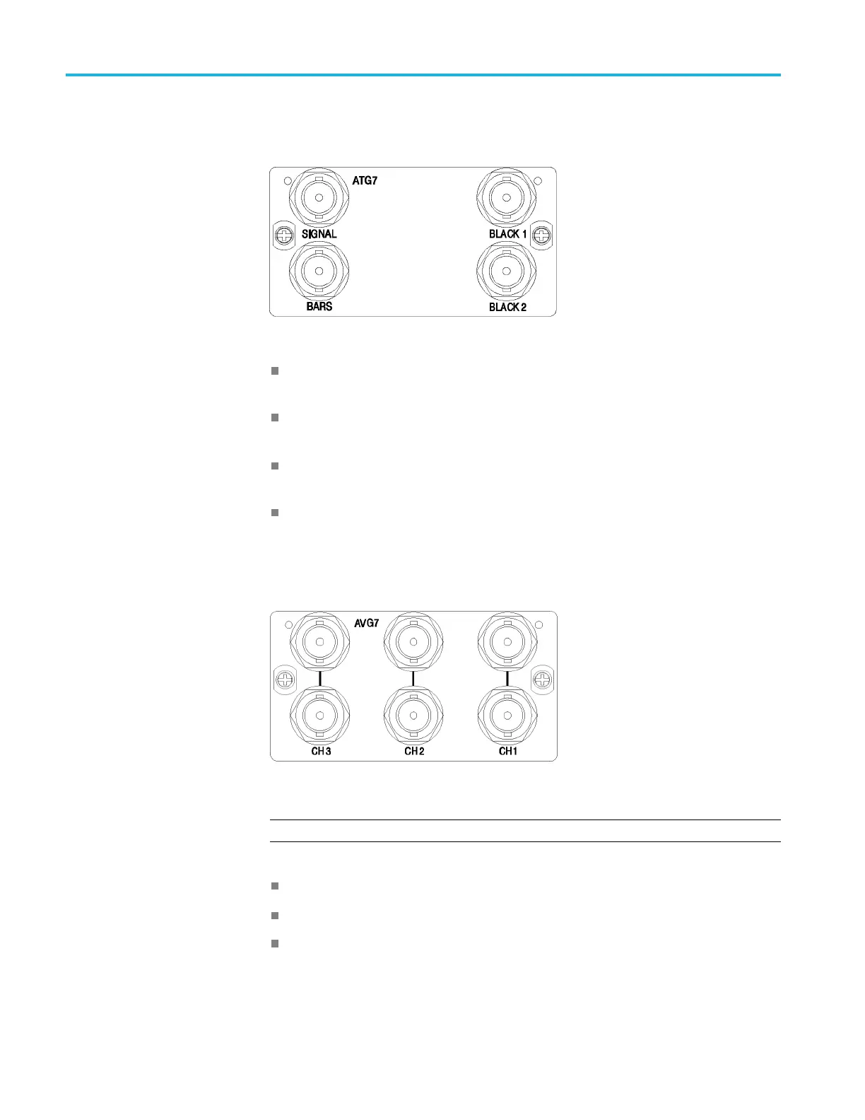
The ATG7 Analog
Test Generator module is equipped with four BNC connectors
as described below. (See Figure 2-7.)
Figure 2-7: ATG7 module connectors
BLACK 1: Outputs the selected black burst, timing pulse, o r subcarrier
signal.
BLACK 2: Outputs the selected black burst, timing pulse, o r subcarrier
signal.
SIGNAL: Outputs the signal selected using the front-panel test signal buttons.
(See Table 3-5 on page 3-20.)
BARS: Outputs the selected black burst or color bars signal.
AVG7 module connectors
The AVG7 Analog Video Generator module is equipped with three p airs of BNC
connectors as described below. (See Figure 2-8.)
Figure 2-8: AVG7 module connectors
N
OTE. Each pair of connectors (CH 1, CH 2, and CH 3) output the same signal.
CH 1: Outputs the selected analog component or composite video signal.
CH 2: Outputs the selected analog component or composite video signal.
CH 3: Outputs the selected analog component or composite video signal.
2–10 TG8000 Multiformat Test Signal Generator User Manual

 Loading...


