AWVG7 Analog Wideband Video Generator module
To select the te st signal
All of the signa
l sets that are available in the module are already assigned to the
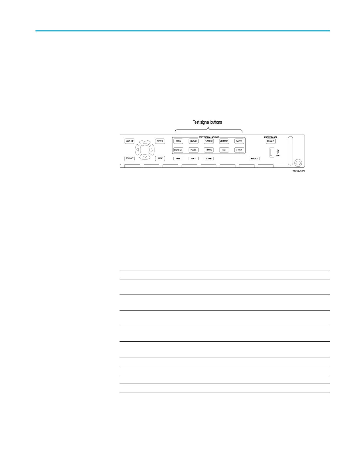
corresponding test signal buttons. When the AWVG7 module is selected and you
press any of the front-panel test signal buttons, the selected signal in the signal set
is output. (See Figure 3-26.)
For example, when you press the COLOR BAR test signal button, a signal in
the Color Bars signal set is output. Use the left (◄)orright(►) arrow button, or
press the COLOR BAR test signal button repeatedly to select a different signal
from the Color Bars signal set.
Figure 3-26: Front-panel test signal buttons
You can download a frame picture file (created by the Frame Picture Generator)
to the mainframe and output the picture from the AWVG7 module. Refer to the
TG8000 PC Tools Technical Reference for detailed information on how to create,
download, and output a frame picture.
The following table lists the AWVG7 signal sets that are assigned to the test signal
buttons and shows the test signals that are available in each signal set.
Table 3-10: AWVG7 module signal sets assigned to the test signal buttons
Button name Signal set Signals in the signal set
COLOR BAR Color Bars 100% Color Bars, 75% Color Bars
LINEARITY Linearity
10 Step, 5 Step, Ramp, Shallow Ramp,
Valid Ramp
1
FLAT FIELD Flat Fields
0% Flat Field, 100% Flat Field, 50%
Flat Field
MULTI BURST
Multi Burst Multiburst 1-10 MHz, Multiburst
10-20 MHz, Multiburst 20-30 MHz
SWEEP Sweep 100% Sweep 1-15 MHz, 100% Sweep
1-30 MHz
MONITOR
Monitor
75% Blue Field, Convergence, 75%
Green Field, 75% Red Field
PULSE BAR Pulse & Bar 2T30 Pulse & Bar
TIMING
Timing Bowtie 1 ns Marker
SDI
—– —–
OTHER
—– —–
1
The Valid Ramp signal is available in YPbPr format only.
TG8000 Multiformat Test Signal Generator User Manual 3–51

 Loading...


