USER’S MANUAL__________________________________________________________________
32 __________________________________________________________________ M211322EN-D
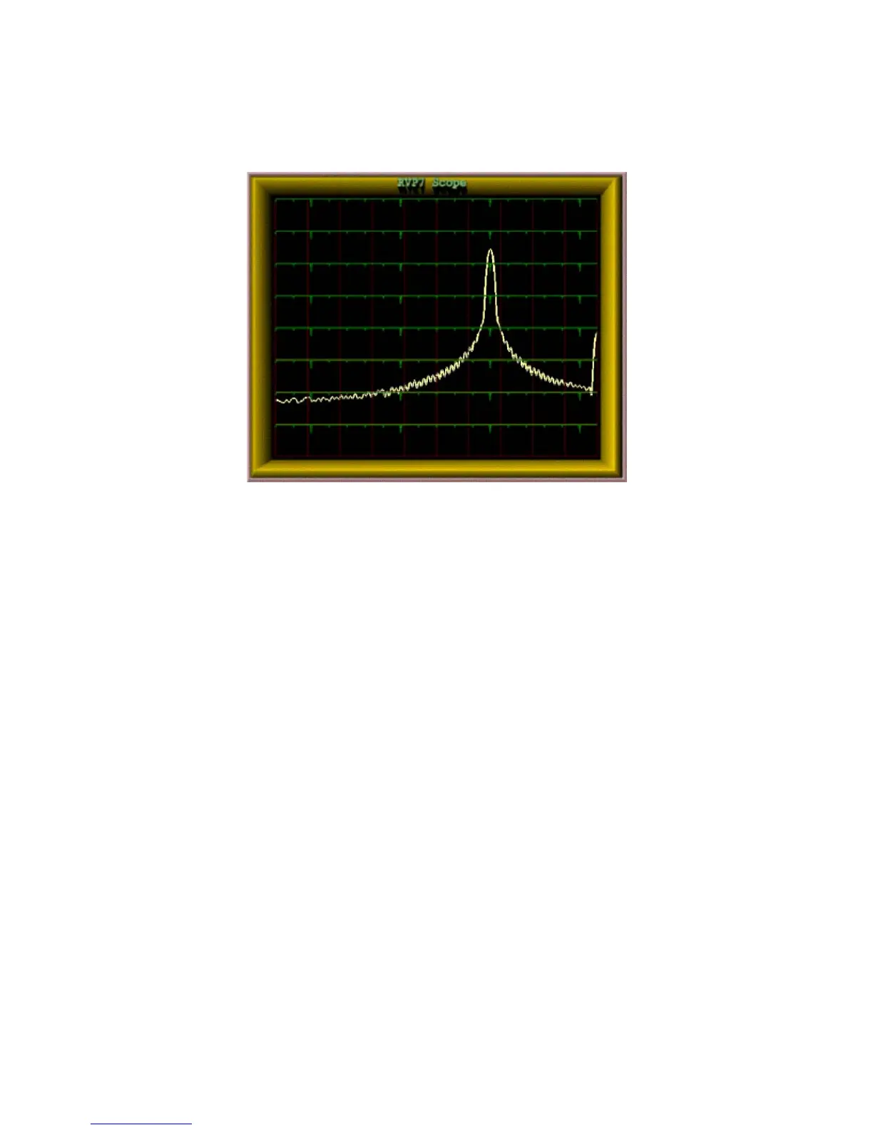
2.6.1.3 Received Signal Spectrum Analysis Tool
0916-010
Figure 9 Received Signal Spectrum Analysis Tool
The RVP900 provides plots of the IF signal versus range as well as
spectrum analysis of the signal as shown in Figure 9.
In the past, these types of displays and tools required that a highly-skilled
engineer transport some very expensive test equipment to the radar site.
Now, detailed analysis and configuration can be done from a central
maintenance facility through the network. For a multi-radar network, this
results in substantial savings in equipment, time, and labor.
2.6.2 Digital Transmitter Function
Many of the exciting new meteorological applications for the RVP900 are
made possible by its ability to function as a digital radar receiver and
transmitter simultaneously. The RVP901 IFDR synthesizes an output
waveform that is centered or offset from the radar’s intermediate
frequency. This signal is filtered using analog components, then
up-converted to RF, and finally amplified for transmission. The actual
transmitter can be a solid state or vacuum tube device. The RVP900 can
even correct for waveform distortion by adaptively "pre-distorting" the
transmit waveform, based on the measured transmit burst sample.
The IFDR has two SMA output for the IF Tx waveform. The digital IF
waveforms are generated by a 16-bit DAC with 65 dB SNR from 10 MHz
 Loading...