USER’S MANUAL__________________________________________________________________
92 __________________________________________________________________ M211322EN-D
The "Inhb" line is held low, and fault status is input on Pin 4. All pins that
are not directly controlled by the software uplink (for example, power pins
and unused pins) are set to "GND" in the setup table.
3.4.2 Example of a MITEQ MFS-05.00–
05.30–100K–10MP STALO
The electrical interface for this STALO uses a 25-pin “D” connector with
the pin assignments (Table 7 on page 90).
First configure the DAFC pins themselves. Pins 1 and 14 are ground, and
are connected with wirewrap wire to the nearby ground posts. Pins 2 and
15 are connected with a wirewrap wire to the +24 V posts, and pint 3 and
16 are connected with wirewrap wire to the +5 V posts. The Alarm on pin
5 is wired to the alarm post. Pins 7 through 13 and pins 17 through 25 all
are signal pins, so we plug in a jumper for each of these 16 pins. We use
pinmap uplink protocol, so H3 and H4 are removed. Also, remove H5 and
leave H1 on.
In this example, we assume that we wish to control the STALO in 100 KHz
steps from 5.1330 GHz to 5.1830 GHz. This can be done with the
following setups from the Mb section:
AFC span– [-100%,+100%] maps into [ 1330 , 1830 ]
AFC format– 0:Bin, 1:BCD, 2:8B4D: 2, ActLow: NO
AFC uplink protocol– 0:Off, 1:Normal, 2:PinMap : 2
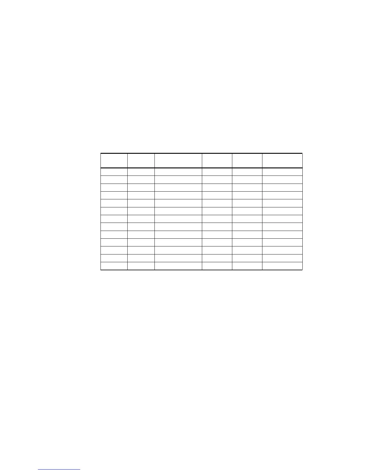
Table 7 Pinout for the MITEQ MFS–xx.xx–xx.xx–100K–xxMP
Synthesizers
Ribbon
Pin
"D" Pin Function Ribbon
Pin
"D" Pin Function
1 1 Ground 2 14 Ground
3 2 +20 VDC 4 15 +20 VDC
5 3 +5.2 VDC 6 16 +5.2 VDC
7 4 Test Point 8 17 10 MHz (1)
9 5 TTL Alarm 10 18 1 MHz (8)
11 6 Phase Voltage 12 19 1 MHz (4)
13 7 100 MHz (8) 14 20 1 MHz (2)
15 8 100 MHz (4) 16 21 1 MHz (1)
17 9 100 MHz (2) 18 22 100 MHz (8)
19 10 100 MHz (1) 20 23 100 MHz (4)
21 11 10 MHz (8) 22 24 100 MHz (2)
23 12 10 MHz (4) 24 25 100 MHz (1)
25 13 10 MHz (2) 26 -- --
 Loading...